BA7078AF/AS
Multimedia ICs
1/12
Synchronization signal processor for
high definition displays
BA7078AF/AS
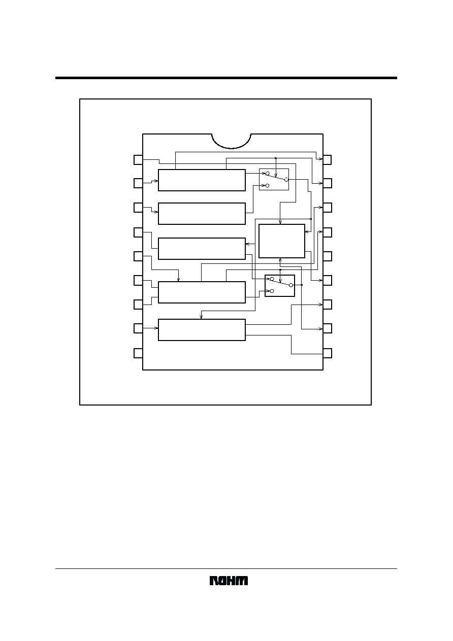
The BA7078AF is a synchronization signal processing LSI chip designed for multiscan high-definition displays. It
generates a synchronization signal and clamp pulse for three types of input signals: separate synchronization, composite
synchronization, and synchronization on video.
!
!
!
!
Application
CRT displays
!
!
!
!
Features
1) Operates on a single 5V power supply, with low power consumption.
2) Synchronization signal existence and polarity detec-tion output.
3) Adjustable clamp pulse width, allowing for the selec-tion of front or back editing.
4) Vertical synchronization separation is based on hori-zontal frequency tracking, for separation starting at 1H.
5) Minimal attached components.
!
!
!
!
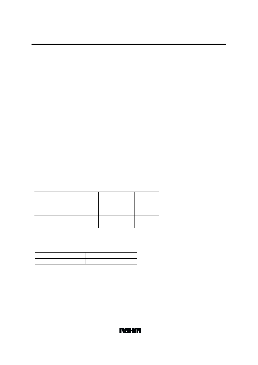
Absolute maximum ratings (Ta = 25
°C)
Power supply voltage
Power dissipation
Storage temperature
Operating temperature
Parameter
Symbol
Limits
Unit
V
CC
Pd
V
mW
7.0
450(BA7078AF)
600(BA7078AS)
°
C
°
C
-
25 to
+
75
-
55 to
+
125
1 Reduced by 4.5mW for each increase in
Ta of 1
°
C over 25
°
C.
2 Reduced by 6.0mW for each increase in
Ta of 1
°
C over 25
°
C.
Topr
Tstg
1
2
!
!
!
!
Recommended operating conditions (Ta = 25
°C)
Parameter
Symbol
Min.
Typ.
Max.
Unit
Power supply voltage
V
CC
4.5
5.0
5.5
V
BA7078AF/AS
Multimedia ICs
3/12
!
!
!
!
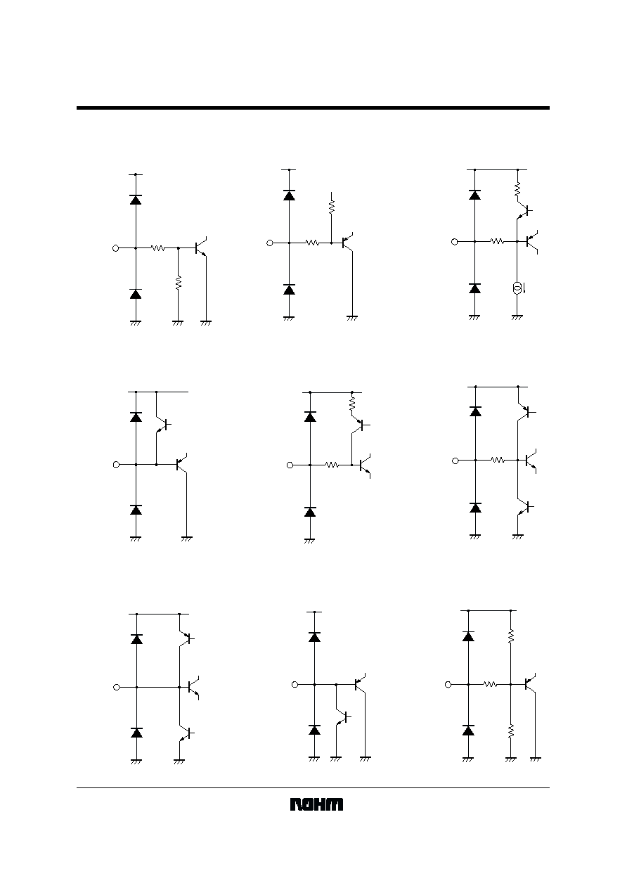
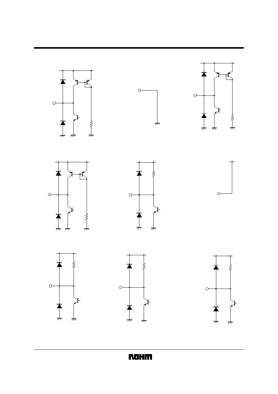
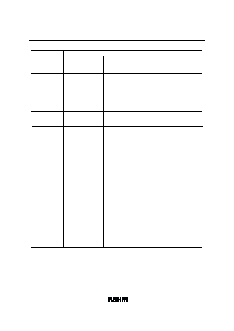
Pin descriptions
Pin name
Pin No.
1
2
HSCTL
C / HSYNC IN
3
VIDEO IN
4
VSEPA
Functions
HDRV output
SYNC ON VIDEO input
Composite sync / H SYNC
input
Used to select whether to output the VDRV section of the HDRV output
signal.
High : VDRV section of HDRV is output
Low : VDRV section of HDRV is not output
Input either the composite synchronization signal or the horizontal
synchronization signal. Input is clamped, and is initiated by capacitor
coupling.
Inputs the SYNC ON VIDEO signal(green).
Input is sink chip clamped. Input is initiated by capacitor coupling.
f-V conversion
5
VSYNC IN
V SYNC input
Converts the horizontal synchronization signal frequency into a voltage.
The voltage generated is proportional to the frequency of the horizontal
synchronization signal. Attach a 0.56
µ
F capacitor between the ground
pins.
Inputs the vertical synchronization signal.
6
CVPOL
Vertical polarity integration
Integrates the vertical synchronization signal polarity detection circuit.
Attach a 1.5
µ
F capacitor between this pin and the ground.
7
CVEXI
Vertical existence integration
8
CPSEL
Setting the clamp position
9
GND
Ground
10
CPWID
Setting the clamp pulse width
11
VDRV
VDRV output
Integrates the vertical synchronization signal existence detection circuit.
Attach a 1
µ
F capacitor between this pin and the ground.
Used to set the clamp pulse generation position to either the front or
back edge of HSYNC
High : The front edge is the generation position
Open : Composite / H SYNC IN : The front edge is the generation position
VIDEO IN
: The back edge is the generation position
Low : The back edge is the generation position
-
14
V
CC
Power supply
-
Sets the clamp pulse width according to the attached time constant.
Attach a resistor between this pin and V
CC
and, a capacitor between
this pin and GND. When R = 3.9k
and C = 100pF, pulse width is
approximately 400 ns. Set the resistor to register an abnormality at 1k
.
Outputs the vertical synchronization signal.
The output signal has positive polarity.
13
HDRV
HDRV output
Outputs the clamp pulse generated from the horizontal synchronization
signal. The output signal has positive polarity.
15
EXIV
Vertical existence output
Indecates whether the vertical synchronization signal exists.
For the output logic, refer to the separate table.
16
POLV
Vertical polarity output
Indicates the polarity of the vertical synchronization signal.
For the output logic, refer to the separate table.
17
EXIH
Horizontal existence output
Indicates whether the horizontal synchronization signal exists.
For the output logic, refer to the separate table.
18
POLH
Horizontal polarity output
Indicates the polarity of the horizontal synchronization signal.
For the output logic, refer to the separate table.
12
CLAMP
Clamp output
Outputs the clamp pulse generated from the vertical synchronization
signal. The output signal has a positive polarity.