1
Video ICs
High-voltage audio head selection
switch
BA7755A / BA7755AF
The standard audio circuits of video cassette recorders and the recording circuits of tape decks use AC bias record-
ing to record the audio signal onto the tape. This bias voltage is some tens of volts, and a high-capacity bias-side
switch is required to electronically switch the head when in playback or record mode.
The BA7755A and BA7755AF are high-voltage switching ICs designed to switch voltages as high as ± 65V
DC
or
AC120V
P-P
(f = 70Hz).
Two control systems, one for current control, and one for voltage control are provided, so the ICs can be used in cir-
cuits that employ either method.
By combining the BA7755A or BA7755AF with the BA7751ALS recording / playback amplifier, it is possible to con-
struct a compact recording / playback audio circuit. In addition, the BA7755A and BA7755AF are an excellent choice
for a wide variety of other high-voltage switching applications.
∑
Applications
Video cassette recorders and tape decks
∑
Features
1) High withstanding voltage ( ± 65V
DC
(Min.),
AC120V
P-P
(Min.), f = 70Hz).
2) Circuits for either current control or voltage control
are provided on the chip.
3) Compact SIP 5pin or SOP 8pin package.
∑
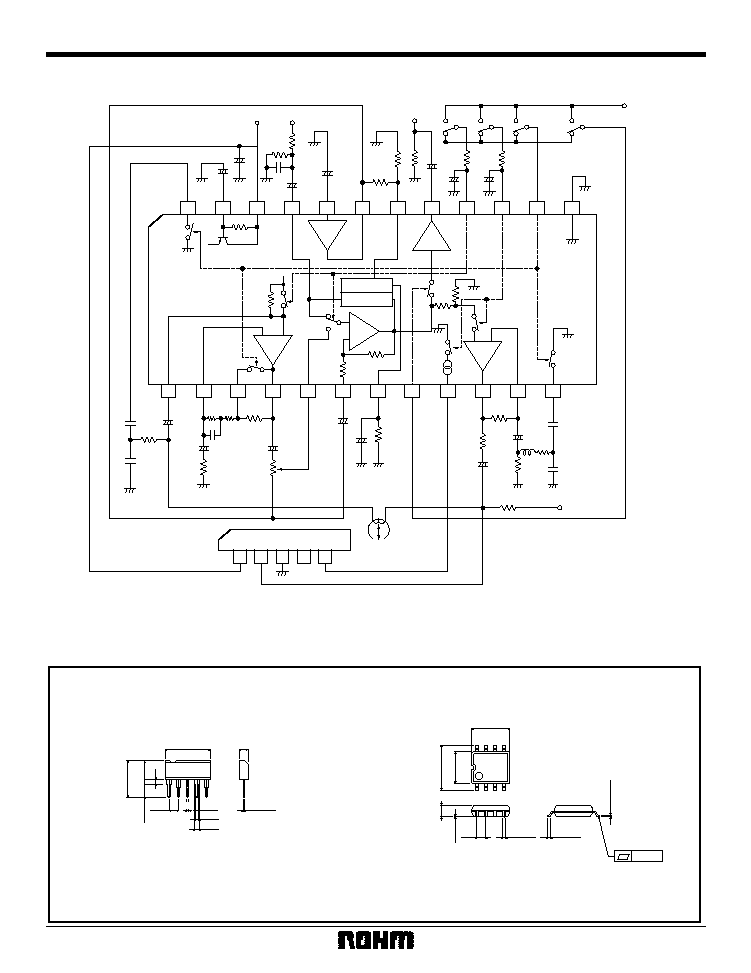
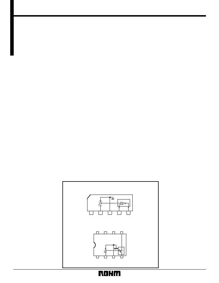
Block diagram
BA7755AF
1
2
3
4
5
SW
GND CTRL2 CTRL1
BA7755A
V
CC
8
7
6
5
1
2
3
4
N.C.
N.C.
N.C.
HEAD
SWITCH
GND CTRL2
CTRL1
V
CC
2
Video ICs
BA7755A / BA7755AF
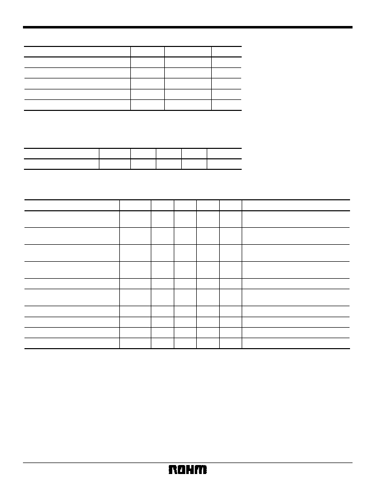
∑
Absolute maximum ratings (Ta = 25∞C)
Parameter
Symbol
Limits
Unit
V
CC
15
V
Pd
400
1
mW
Topr
≠ 10 ~ + 65
∞
C
Tstg
≠ 55 ~ + 125
∞
C
BV
CC2
±
65
V
Reduced by 4mW for each increase in Ta of 1
∞
C over 25
∞
C.
Power supply voltage
Power dissipation
Operating temperature
Storage temperature
Breakdown voltage of switch (pin 2)
∑
Recommended operating conditions (Ta = 25∞C)
Parameter
Unit
V
Max.
13
9
Typ.
Min.
4
Symbol
V
CC
Operating voltage
∑
Electrical characteristics (unless otherwise noted, Ta = 25∞C and V
CC
= 9V)
Parameter
Symbol
Min.
Typ.
Max.
Unit
Conditions
I
CC1
--
0
10
µ
A
Pin4 "L" or "OPEN"
Pin5 "OPEN"
I
CC2
2.4
3.9
5.6
mA
Pin 4 "L" or "OPEN"
Pin 5 control current: 200
µ
A
R
ON
--
8.0
15.0
Pin 4 "L" or "OPEN"
Pin 5 control current: 200
µ
A
I
LOFF
--
0
10
µ
A
Pin 4 "H", or "OPEN", or "L"
Pin 5 "OPEN", pin 2 applied voltage
±
65V
BV
AC
120
160
--
V
P-P
f = 70kHz
V
OS
--
4.3
15.0
mV
Pin 4 "L" or "OPEN"
Pin 5 control current: 200
µ
A
I
CTRL1 (ON)
50
--
--
µ
A
--
I
CTRL1 (OFF)
--
--
1
µ
A
--
V
TH1
1.70
2.15
2.60
V
--
R
CTRL2
21.0
31.0
42.0
k
--
Supply current
Supply current
Switch-on resistance
Switch leakage current
Switch AC breakdown voltage
Switch offset voltage
CTRL1 SW ON control current
CTRL1 SW OFF control current
CTRL2 threshold voltage
CTRL2 input resistance
3
Video ICs
BA7755A / BA7755AF
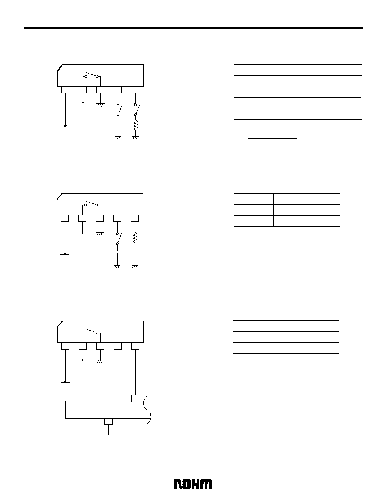
∑
Switch control methods
(1) Control with pins 4 and 5
BA7755A
1
2
3
4
5
SW1
SW2
5V
R
V
CC
Fig. 1
Head
SW2
OFF
ON
OFF
ON
SW1
OFF
ON
R
≠10 [k
]
Between pins 2 and 3
V
CC ≠
1.4
[V]
200 [
µ
A]
High impedance
Low impedance
High impedance
High impedance
When V
CC
= 9V (approx) R
28k
SW1
OFF
ON
Between pins 2 and 3
Low impedance
High impedance
(2) Control with pin 4 only
BA7755A
1
2
3
4
5
SW1
5V
R
V
CC
Fig. 2
Head
REC / EEE
EE (L)
REC (H)
Between pins 2 and 3
Low impedance
High impedance
(3) When used with the BA7751ALS
BA7755A
1
2
3
4
5
BA7751ALS
17
20
V
CC
REC / EE
Fig. 3
Head