 | –≠–ª–µ–∫—Ç—Ä–æ–Ω–Ω—ã–π –∫–æ–º–ø–æ–Ω–µ–Ω—Ç: BA7787FS | –°–∫–∞—á–∞—Ç—å:  PDF PDF  ZIP ZIP |
1
Multimedia ICs
Headphone / speaker amplifier for
notebook computers
BA7786FP-Y / BA7787FS
The BA7786FP-Y and BA7787FS are sound amplifiers designed for notebook computers, and contain a suspend
function and input pins for the system beep and PM beep sounds used by notebook computers. In short, this single-
chip IC contains all the analog audio components needed for notebook computers.
∑
Applications
Notebook computers
∑
Features
1) Stereo headphone amplifier that supports mixing
input, along with a stereo speaker amplifier
(BA7786FP-Y) or BTL monaural speaker amplifier
(BA7787FS).
2) Internal anti-pop circuit, to prevent the popping sounds
that occur when the power is turned on and off.
3) Internal electronic volume switch and mute circuit.
4) Separate suspend modes for the headphone amplifi-
er and speaker amplifier, for low-power-consumption
computers .
5) Two beep input pins, a necessity for notebook com-
puters.
∑
Absolute maximum ratings (Ta = 25∞C)
∑
Recommended operating conditions (Ta = 25∞C)
Parameter
Symbol
Limits
Unit
Power supply voltage
V
CC
V
6
Power
dissipation
mW
850
1
Pd
600
2
Operating temperature
Topr
Tstg
∞
C
∞
C
≠ 10 ~ + 70
Storage temperature
≠ 55 ~ + 125
BA7786FP-Y
BA7787FS
1 Reduced by 6.8mW for each increase in Ta of 1
∞
C over 25
∞
C.
2 Reduced by 6.0mW for each increase in Ta of 1
∞
C over 25
∞
C.
Parameter
Symbol
Typ.
Unit
Power supply voltage
V
CC
V
Min.
Max.
4.5
5.0
5.5
Product
S.P.amp
Other functions
BA7786FP-Y
BA7787FS
H.P.amp
Stereo
Stereo
Stereo
Monaural
SYSTEM / PM BEEP input, SUSPEND, EVR, MUTE,
BEEP level control
2
Multimedia ICs
BA7786FP-Y / BA7787FS
∑
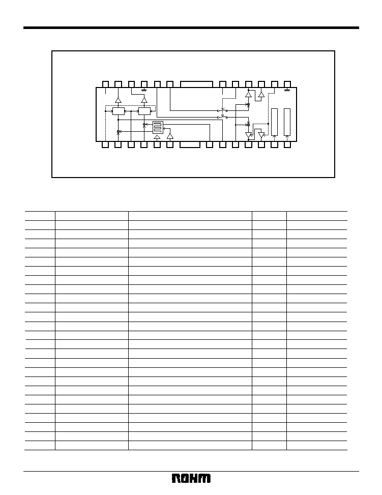
Block diagram
HP SUSPEND
SP SUSPEND
HP V
CC
SP V
CC
HP V
CC
HP OUT R
HP GND
SP IN L
SP IN R
HP OUT L
SP V
CC
LINE MIX ON / OFF
SP OUT1 R
SP OUT2 R
MONO / ST
SP GND
EVR CTRL
LINE IN L
MUTE CTRL
LINE IN R
BIAS
SYSTEM BEEP IN
LCH OUT
BEEP LEVEL
PM BEEP IN
SP OUT1 L
SP OUT2 L
HP SUSPEND
SP SUSPEND
1
2
3
4
5
6
7
8
9
10
11
12
13
14
15
16
17
18
19
20
21
22
23
24
25
VR
VR
BA7786FP-Y
∑
Pin descriptions
Pin No.
Pin name
Function
1
2
3
4
5
6
7
8
9
10
11
12
13
14
15
16
17
18
19
20
21
22
23
24
EVR CTRL
EVR control pin
25
Voltage
Type
--
B (NPN)
LINE IN L
Line Lch input
2.5
B (PNP)
MUTE CTRL
Headphone mute control pin
5.0
100k
PULL UP
LINE IN R
Line Rch input
2.5
B (PNP)
BIAS
Bias
2.5
23.5k
SYSTEM BEEP IN
SYSTEM BEEP input
2.5
B (NPN)
BEEP LEVEL
SYSTEM BEEP IN output level setting
4.2
C (PNP) ~ 3k
LCH OUT
LINE IN L + SYSTEM BEEP IN output
--
C (PNP)
PM BEEP IN
PM beep input
2.5
B (NPN)
SP OUT1 L
BTL speaker Lch output (forward)
2.5
EF (NPN)
SP OUT2 L
BTL speaker Lch output (reverse)
2.5
EF (NPN)
HP SUSPEND
Headphone SUSPEND control
5.0
100k
PULL UP
SP SUSPEND
Speaker SUSPEND control
5.0
100k
PULL UP
SP GND
Speaker ground
0.0
--
MONO / ST
Speaker amplifier Lch ON / OFF control
5.0
100k
PULL UP
SP OUT2 R
BTL speaker Rch output (reverse)
EF (NPN)
SP OUT1 R
BTL speaker Rch output (forward)
2.5
EF (NPN)
LINE MIX ON / OFF
SP IN L / R input ON / OFF control
5.0
100k
PULL UP
SP V
CC
Speaker Vcc
5.0
--
SP IN R
Speaker Rch input
2.5
B (NPN)
SP IN L
Speaker Lch input
2.5
B (NPN)
HP GND
Headphone ground
0.0
--
HP OUT R
Headphone Rch output
2.5
EF (NPN)
HP OUT L
Headphone Lch output
2.5
EF (NPN)
HP V
CC
Headphone Vcc
5.0
--
2.5
Note) The pin formats are as follows. EF: emitter follower; B: base; C: collector; ~ : series connection.
The above values are all based on the settings (HP V
CC
= SP V
CC
= + 5.0V) in Fig. 1, entitled "Measurement circuit diagram,"
and do not guarantee standards.
BA7786FP-Y
3
Multimedia ICs
BA7786FP-Y / BA7787FS
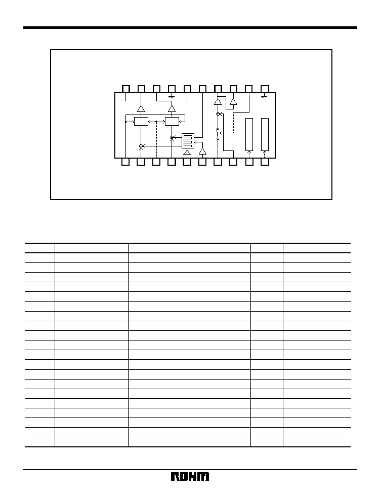
∑
Block diagram
20
19
18
17
16
15
11
1
2
3
4
5
6
9
10
HP V
CC
HP V
CC
HP OUT R
HP GND
SP V
CC
BEEP LEVEL
HP OUT L
SP GND
EVR CTRL
LINE IN L
MUTE CTRL
LINE IN R
BIAS
SYSTEM BEEP IN
SP SUSPEND
HP SUSPEND
14
SP OUT1
13
SP OUT2
12
LINE MIX ON / OFF
7
SP IN
8
PM BEEP IN
SP V
CC
HP SUSPEND
SP SUSPEND
VR
VR
BA7787FS
1
EVR CTRL
EVR control pin
2
LINE IN L
Line Lch input
B (PNP)
B (PNP)
23.5k
B (NPN)
B (NPN)
B (NPN)
B (PNP)
B (PNP)
EF (NPN)
EF (NPN)
EF (NPN)
--
--
EF (NPN)
--
B (NPN)
3
MUTE CTRL
Headphone mute control
100k
PULL UP
4
LINE IN R
Line Rch input
5
BIAS
Bias
6
SYSTEM BEEP IN
SYSTEM BEEP input
7
SP IN
Speaker input
8
PM BEEP IN
PM BEEP input
9
HP SUSPEND
Headphone SUSPEND control
10
SP SUSPEND
Speaker SUSPEND control
11
SP GND
Speaker ground
12
LINE MIX ON / OFF
SP IN input ON / OFF control
100k
PULL UP
C (PNP) ~ 3k
13
SP OUT2
BTL speaker output (reverse)
14
SP OUT1
BTL speaker output (forward)
15
BEEP LEVEL
16
SP V
CC
Speaker Vcc
17
HP GND
Headphone ground
18
HP OUT R
Headphone Rch output
19
HP OUT L
Headphone Lch output
20
HP V
CC
Headphone Vcc
--
SYSTEM BEEP IN output level setting
Pin No.
Pin name
Function
Pin voltage
Pin type
--
2.5
5.0
2.5
2.5
2.5
2.5
2.5
--
--
0.0
5.0
2.5
2.5
4.2
5.0
0.0
2.5
2.5
5.0
Note) The pin formats are as follows. EF: emitter follower, B: base, C: collector, ~ : series connection.
The above values are all based on the settings (HP V
CC
= SP V
CC
= + 5.0V) in Fig. 2, entitled "Measurement circuit diagram,"
and do not guarantee standards.
BA7787FS
4
Multimedia ICs
BA7786FP-Y / BA7787FS
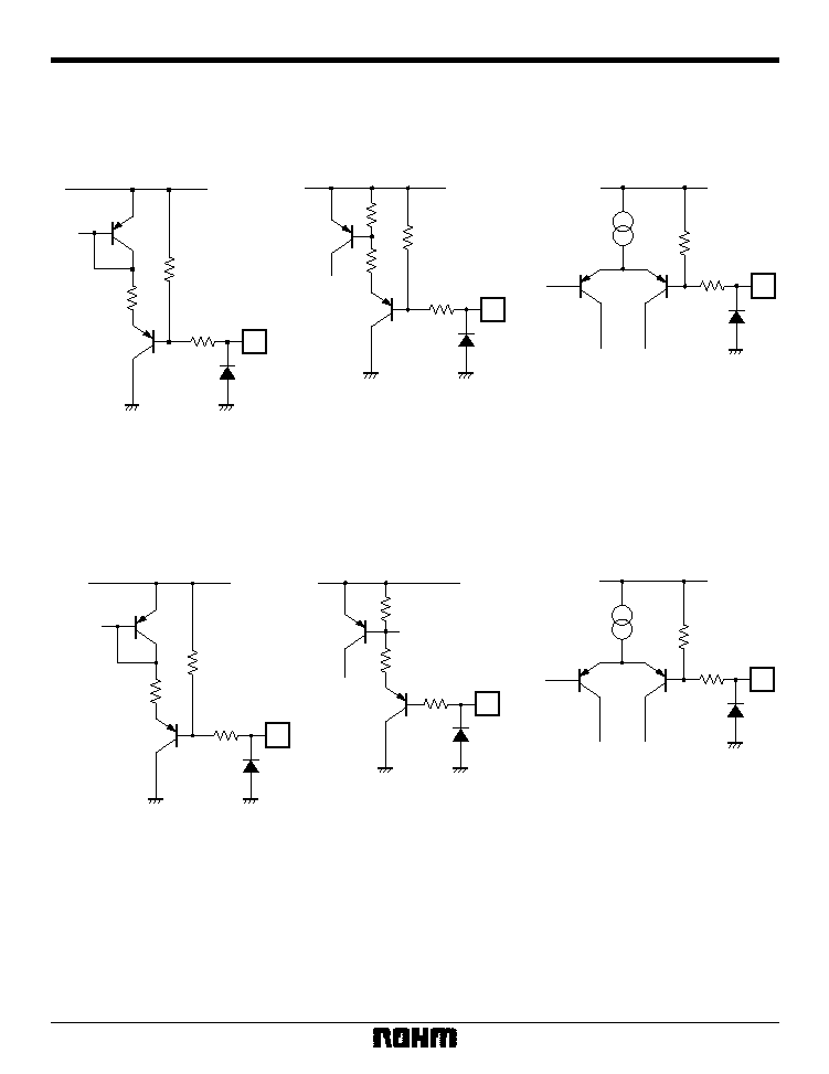
∑
Control pin circuits
100k
3,15pin
10k
HP V
CC
BA7786FP-Y
MUTE CTRL (3pin)
MONO / ST (15pin)
100k
12,13pin
10k
HP V
CC
HP SUSPEND (12pin)
SP SUSPEND (12pin)
20k
100k
18pin
HP V
CC
LINE MIX ON / OFF (18pin)
100k
3pin
10k
HP V
CC
BA7787FS
MUTE CTRL (3pin)
Note) All figures are design values, and do not represent guaranteed performance.
10k
9,10pin
HP V
CC
HP SUSPEND (9pin)
SP SUSPEND (10pin)
20k
100k
12pin
HP V
CC
LINE MIX ON / OFF (12pin)
5
Multimedia ICs
BA7786FP-Y / BA7787FS
Parameter
Symbol
Unit
Conditions
Min.
Typ.
Max.
Supply current
Supply current
Supply current SUSPEND
Output voltage level
Maximum output level
Output residual noise
Interchannel crosstalk
Muting level
Output voltage level
Input threshold level
Output voltage level
Distortion
Maximum output level
Output residual noise
Interchannel crosstalk
LINE MIX OFF level
Output level
MUTE CTRL
(pin 13)
HP MUTE ON holding voltage
HP MUTE OFF holding voltage
HP SUSPEND
(pin 12)
HP SUSPEND holding voltage
HP SUSPEND holding voltage
SP SUSPEND
(pin 13)
HP SUSPEND holding voltage
HP SUSPEND holding voltage
MONO / STEREO
(pin 15)
MONAURAL holding voltage
STEREO holding voltage
LINE MIX ON / OFF
(pin 18)
LINE MIX OFF holding voltage
LINE MIX ON holding voltage
EVR variation range
Distortion
Measurement circuit
3.52
4.82
7.64
No input, SP OUT = no load
Fig.1
I
CC
mA
175
240
410
No input, V
H
= V
S
= H
Fig.1
I
CCS
µ
A
HP AMP 1
INPUT: LINE IN L / R, OUTPUT: HP OUT L / R
HP AMP 2
INPUT: SYSTEM BEEP IN, OUTPUT: HP OUT L / R
SP AMP 2
INPUT: PM BEEP IN, OUTPUT: SP OUT L / R
≠ 7.4
≠ 4.0
≠ 1.5
V
IN
= ≠ 10.0dBV
V
IN
= ≠ 10.0dBV
1
V
IN
= ≠ 10.0dBV
2
V
E
= HP V
CC
V
E
= ground level differential
Fig.1
V
OHP
dBV
--
0.1
1.0
Fig.1
THD
HP
%
≠ 1.6
+ 0.6
--
THD = 1%
1
Fig.1
V
OMHP
dBV
dBV
dBV
dBV
V
P-P
V
P-P
dBV
70
90
--
Fig.1
G
EVR
dB
--
≠ 80
≠ 73
R
g
= 1k
2
V
IN
= ≠ 7.0dBV
2
V
IN
= ≠ 7.0dBV
2
, V
M
= L
V
IN
= ≠ 10.0dBV
V
IN
= ≠ 10.0dBV
1
V
IN
= ≠ 12.0dBV
2
V
IN
= ≠ 12.0dBV
2
, V
L
= L
V
IN
= ≠ 10.0dBV
Fig.1
V
ONHP
--
≠ 79
≠ 70
Fig.1
CT
HP
--
≠ 94
≠ 83
Fig.1
MT
HP
0.22
0.32
0.42
V
IN
= 5.0V
P-P
Fig.1
4.5
--
5.0
Fig.1
V
HBH
V
OSP
THD
SP
V
OHB
≠ 1.4
+ 2.0
+ 4.5
Fig.1
--
0.4
1.5
Fig.1
%
+ 3.5
+ 5.7
--
THD = 1%
1
Fig.1
V
OMSP
dBV
--
≠ 90
≠ 80
R
g
= 1k
2
Fig.1
V
ONSP
dBV
dBV
dBV
dBV
--
≠ 78
≠ 70
Fig.1
CT
SP
--
≠ 78
≠ 70
Fig.1
V
OOFFSP
≠ 7.4
≠ 4.0
≠ 1.5
Fig.1
Fig.1
Fig.1
V
OSB
GND
--
0.4
V
ML
V
4.3
--
V
CC
V
MH
V
GND
--
0.4
Fig.1
V
HL
V
4.3
--
V
CC
Fig.1
V
HH
V
4.3
--
V
CC
Fig.1
V
SH
V
GND
--
0.4
Fig.1
V
SL
V
4.3
--
V
CC
Fig.1
V
NH
V
GND
--
0.4
Fig.1
V
NL
V
GND
--
0.4
Fig.1
V
LL
V
4.3
--
V
CC
Fig.1
V
LH
V
SP AMP 1
INPUT: SP IN L / R, OUTPUT: SP OUT L / R
1
: B.W. = 0.4 ~ 30kHz
2
: DIN audio mode settings are as follows, unless otherwise noted:
V
E
= HP V
CC
(EVR = Max.), V
M
= H (HP MUTE OFF), V
H
= L (HP SUSPEND), V
S
= L (SP SUSPEND), V
L
= H (LINE MIX ON), V
N
= H (STEREO)
BA7786FP-Y
∑
Electrical characteristics (unless otherwise noted, Ta = 25∞C, HP V
CC
= SP V
CC
= 5.0V, f = 1kHz)