300
Communication ICs
Pseudo inductance for telephones
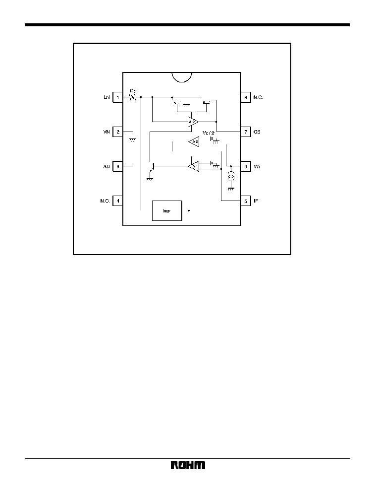
BA8201 / BA8201F
The BA8201 and BA8201F are ICs with a choke coil action, capable of extracting the DC current from a telephone line
while maintaining a high inductance on the telephone line side. This eliminates the need for a choke coil, and facilitates
use of the telephone set line in a variety of applications.
F
Applications
Household telephones
F
Features
1) Corresponds to choke coil of several henries.
2) Extracts DC current while maintaining high induc-
tance on telephone line side.
3) Capable of extracting large output current.
4) Wide dynamic range.
5) Two output voltage modes available for selection.
S
Line voltage seek mode
S
Constant voltage mode
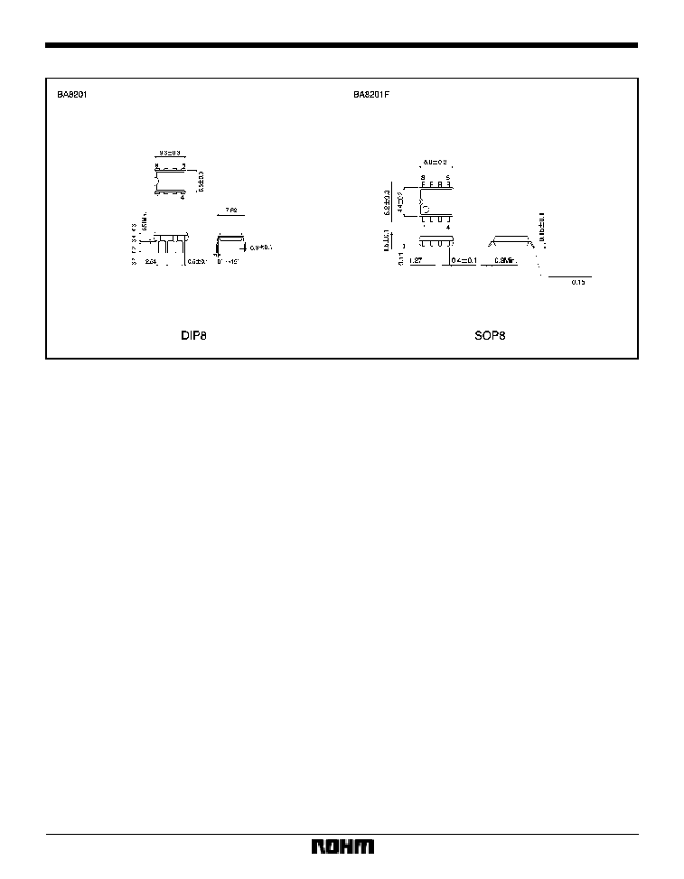
6) DIP 8 and SOP 8 pin packages available.
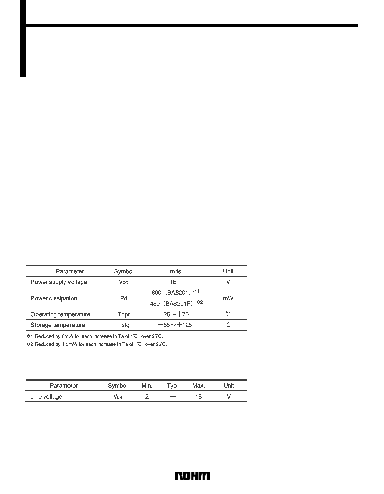
F
Absolute maximum ratings (Ta = 25
_
C)
F
Recommended operating conditions (Ta = 25
_
C)
303
Communication ICs
BA8201 / BA8201F
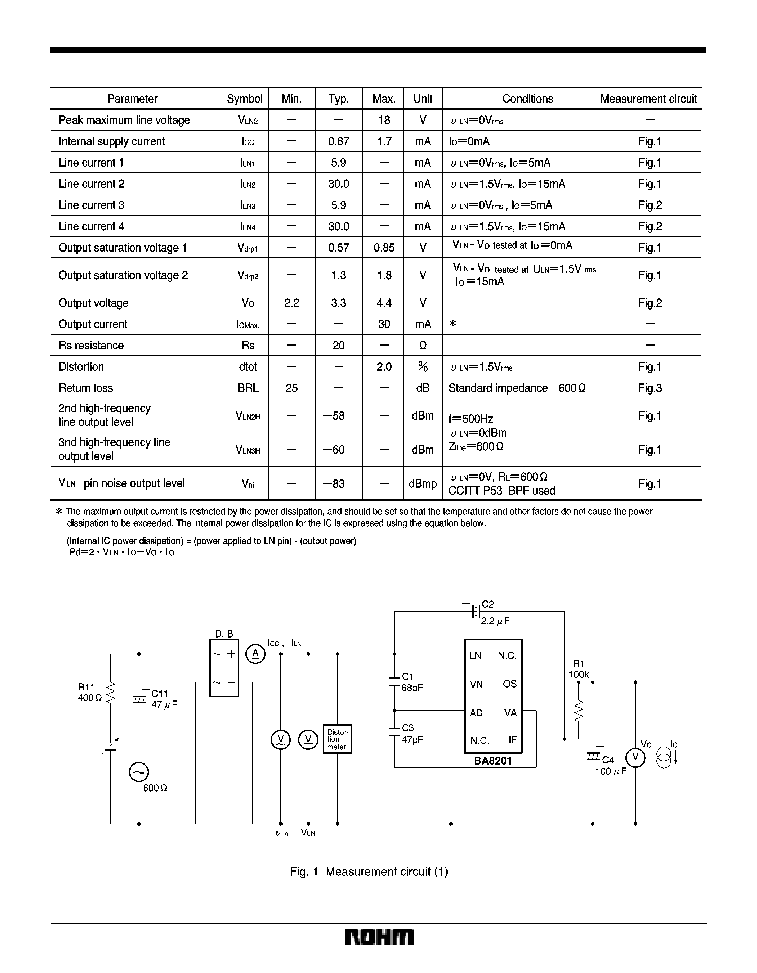
F
Electrical characteristics (unless otherwise noted, Ta = 25
_
C, V
LN
= 4V,
LN
= 100mVrms, Io = 5mA, f = 1kHz)
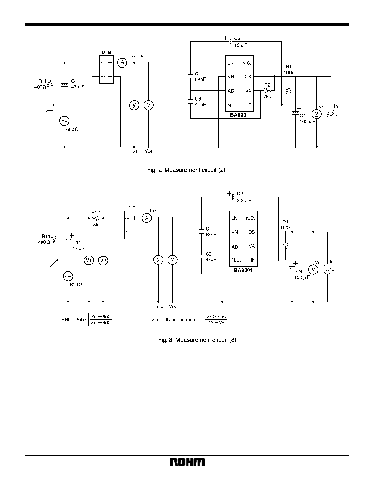
F
Measurement circuits
305
Communication ICs
BA8201 / BA8201F
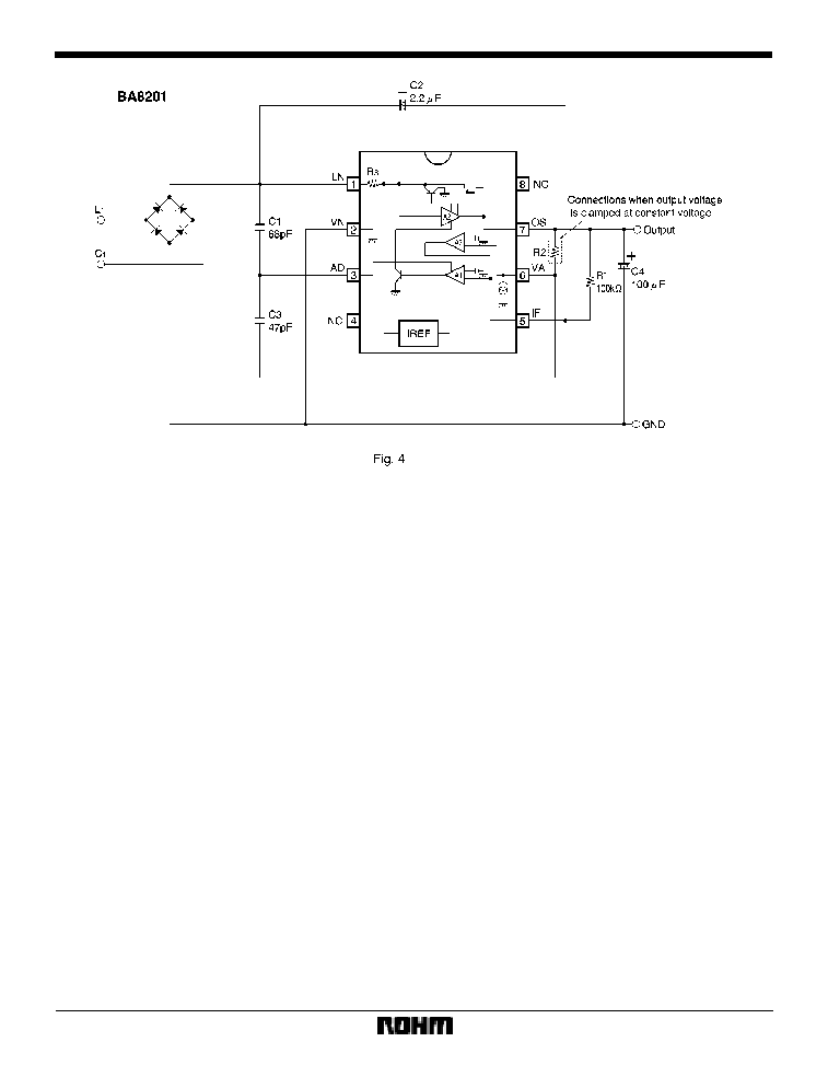
F
Application example
F
Attached components
C1:
This is a capacitor for phase compensation, and is nor-
mally connected at 68pF.
C2:
This is a coupling capacitor. The inductance from the
telephone line changes based on this value. Normally, a
value of 2.2
µ
F to 10
µ
F is appropriate.
C3:
This is a capacitor for phase compensation, and is nor-
mally connected at 47pF.
C4:
This is the capacitor for balancing the output. It sup-
presses rippling in the output and also carries out de-
coupling for the bias voltage supply of the IF pin. It should
be adjusted based on the output current, load, and other
factors.
R1:
Bias is applied from this pin to the IF pin. The inductance
from the telephone line changes based on this value.
Normally, a value of 100k
is appropriate.
R2:
This can be connected between Pins 6 and 7 to clamp the
output voltage. The output voltage is expressed using the
equation below.
Vo (V) = 2
22 (
µ
A)
R2 (
) (reference value)
22
µ
A is the reference internal current source for
the IC.