KTR18
Resistors
1/6
Endured high voltage fixed thick film chip resistors
KTR18 (3216 size: 1 / 4W)
Features
1) Power rating of 1 / 4W
2) Limiting element voltage of KTR series is twice compared with that of MCR series.
3) Highly reliable chip resistor Ruthenium oxide dielectric offers superior resistance to the elements.
4) ROHM resistors have approved ISO≠9001 certification.
Design and specifications are subject to change without notice. Carefully check the specification sheet before using or
ordering it.
Ratings
0.25W (1 / 4W)
-
55
∞
C to
+
155
∞
C
400V
at 70
∞
C
Item
Conditions
Specifications
Rated power
Rated voltage
Operating temperature
Nominal resistance
See Table 1.
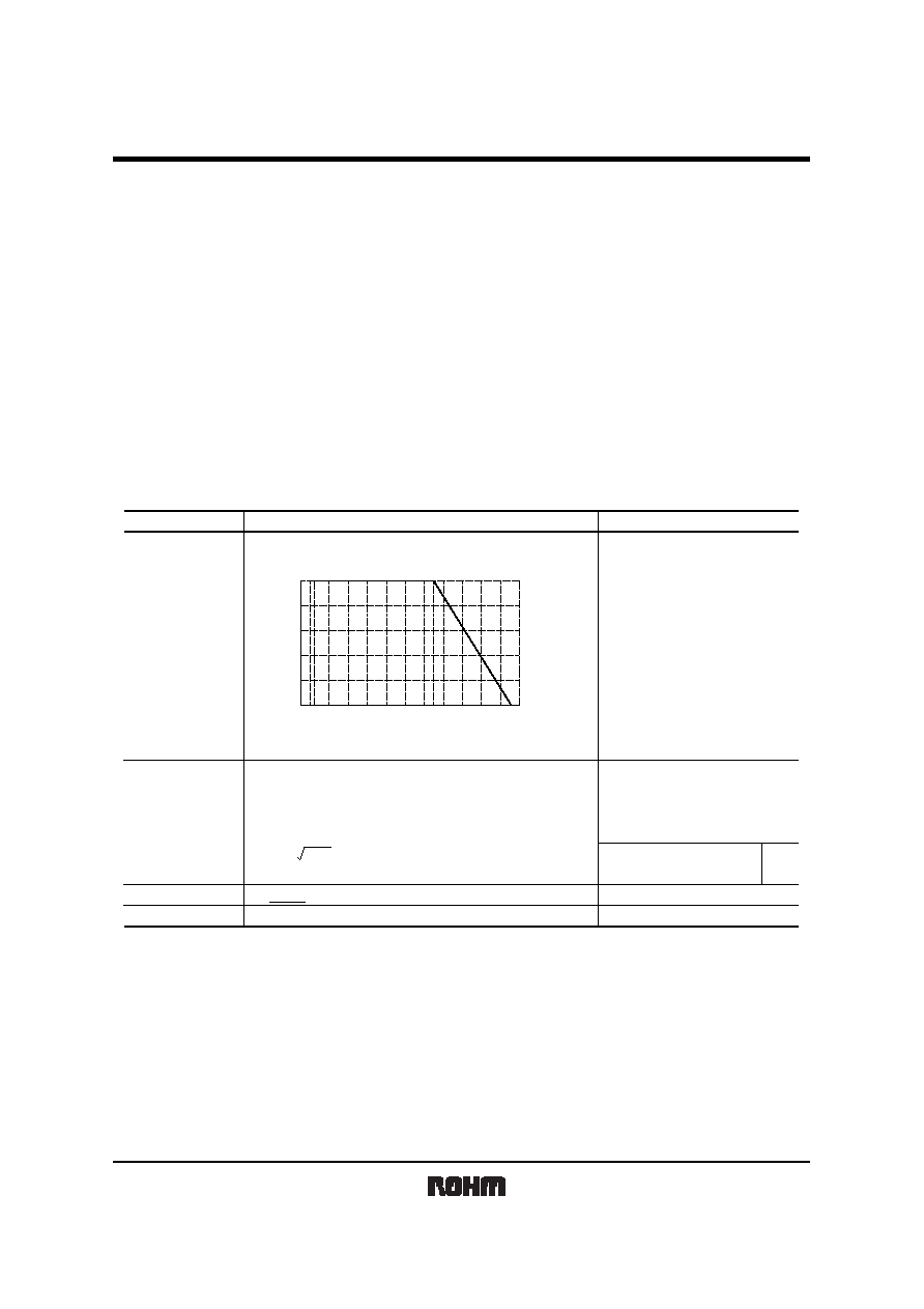
Limiting element voltage
Power must be derated according to the power derating curve in
Figure 1 when ambient temperature exceeds 70
∞
C.
The voltage rating is calculated by the following equation.
If the value obtained exceeds the limiting element voltage,
the voltage rating is equal to the maximum operating voltage.
E: Rated voltage (V)
P: Rated power (W)
R: Nominal resistance (
)
E
=
P
◊
R
0
20
40
60
80
100
-
55
0
70
100
155
AMBIENT TEMPERAT
URE (
∞
C)
POWER LOAD (%)
Fig.1
KTR18
Resistors
2/6
Table 1
Resistance tolerance
Resistance range
(
)
Resistance temperature coefficient
(ppm /
∞
C)
F (
±
1%)
J (
±
5%)
5.6
R
10M
5.6
R
10M (E24,96)
(E24)
±
100
±
200
Before using components in circuits where they will be exposed to transients such as pulse loads (short≠duration, high≠level loads), be certain to evaluate the
component in the mounted state. In addition, the reliability and performance of this component cannot be guaranteed if it is used with a steady state voltage that
is greater than its rated voltage.
Characteristics
Item
Test conditions (JIS C 5201-1)
Resistor type
Guaranteed value
Resistance
Variation of resistance
with temperature
Solderability
Damp heat, steady state
Endurance at 70
∞
C
Endurance
Rapid change of
temperature
Bend strength of
the end face plating
Resistance to solvent
Resistance to
soldering heat
Overload
±
(2.0%
+
0.1
)
±
(3.0%
+
0.1
)
J :
±
5%
F :
±
1%
±
(1.0%
+
0.05
)
No remarkable abnormality on the appearance.
A new uniform coating of minimum of
95% of the surface being immersed
and no soldering damage.
JIS C 5201-1 4.5
JIS C 5201-1 4.8
Measurement :
-
55 /
+
25 /
+
125
∞
C
JIS C 5201-1 4.18
Soldering condition : 260
±
5
∞
C
Duration of immersion : 10
±
1s.
JIS C 5201-1 4.24
40
∞
C, 93%RH
Test time : 1,000h to 1,048h
±
(3.0%
+
0.1
)
±
(3.0%
+
0.1
)
±
(1.0%
+
0.05
)
±
(1.0%
+
0.05
)
Without mechanical damage such as breaks.
±
(1.0%
+
0.05
)
JIS C 5201-1 4.25.1
Rated voltage (current), 70
∞
C
1.5h : ON
-
0.5h : OFF
Test time : 1,000h to 1,048h
JIS C 5201-1 4.25.3
155
∞
C
Test time : 1,000h to 1,048h
JIS C 5201-1 4.29
23
±
5
∞
C, Immersion cleaning, 5
±
0.5min.
Solvent : 2-propanol
JIS C 5201-1 4.19
Test temp. :
-
55
∞
C to
+
125
∞
C 5cyc
JIS C 5201-1 4.33
JIS C 5201-1 4.17
Rosin∑Ethanol (25%WT)
Soldering condition : 235
±
5
∞
C
Duration of immersion : 2.0
±
0.5s.
JIS C 5201-1 4.13
Rated voltage (current)
◊
2.5, 2s.
Limiting Element Voltage
◊
2 : 800V
See Table.1
KTR18
Resistors
3/6
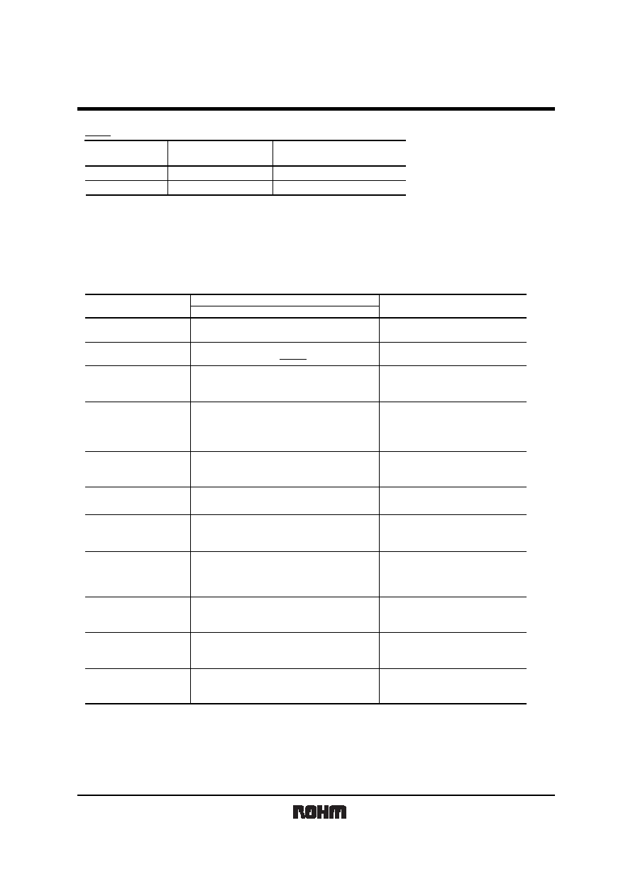
External dimensions (Unit : mm)
0.3
±
0.25
1.6
±
0.15
0.55
±
0.1
0.5
±
0.25
3.2
±
0.15
No.
Material
Thick film resistive element
Silver thick film electrode
Nickel electrode
Sn electrode
Alumina substrate
Overcoating
1
2
3
4
5
6
1
2
4
5
6
3
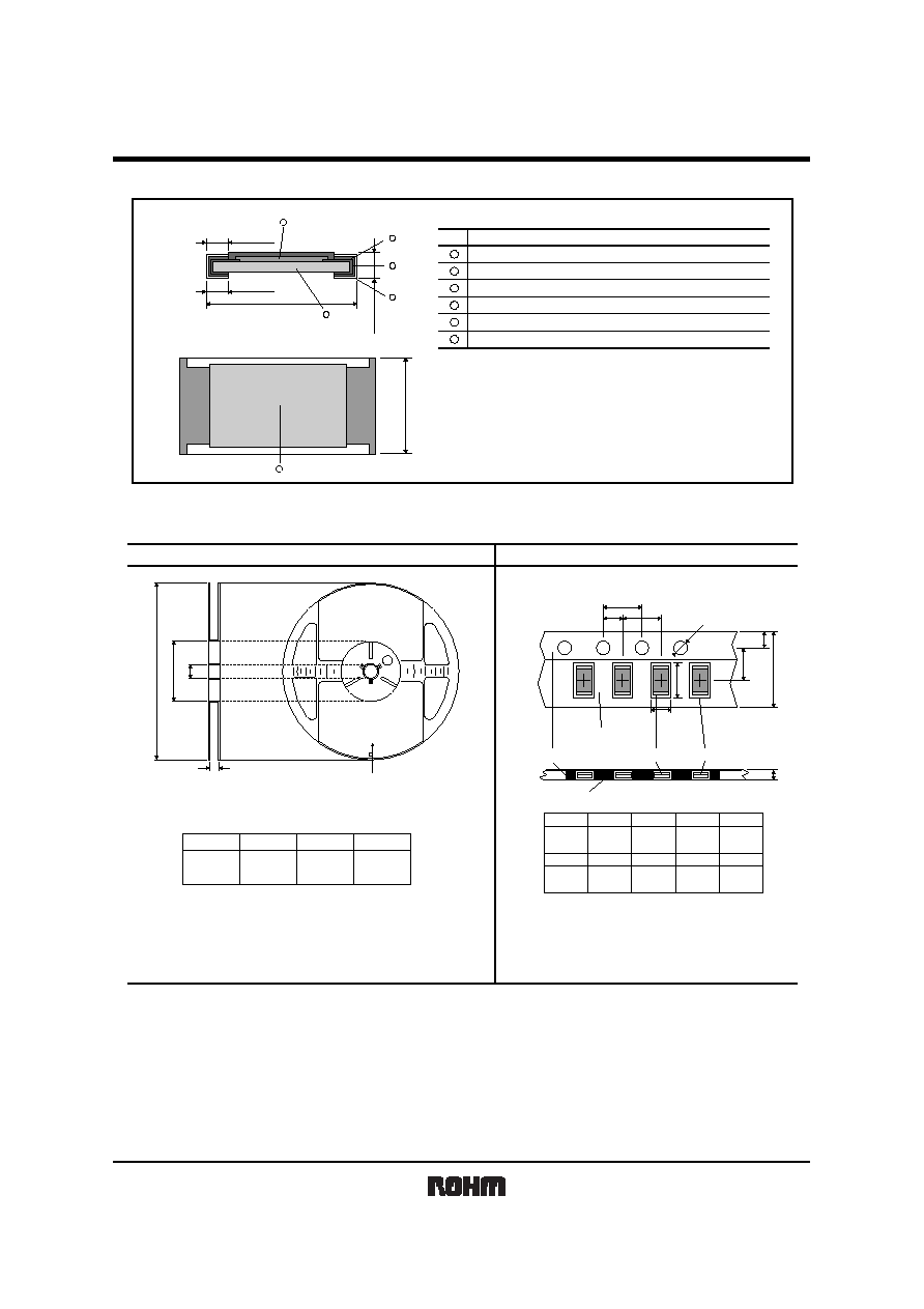
Packaging
0 2
0 4
0 6
0 8
0 2
0 4
0 6
0 8
C
A
B
D
A
B
C
D
P
0
P
2
P
2
E
F
W
T
2
D
2
A
2
B
2
Label
EIAJ ET-7200B compliant
Thick paper
mount
(Underside paper tape)
Chip resistor Square punchout hole
Heat crimp cover/Tape
180
0
-
1.5
60
+1
0
9
+1.0
0
13
±
0.2
4.0
±
0.1
4.0
±
0.1
2.0
±
0.05
Max. 1.1
1.5
+0.1
0
8.0
±
0.3
3.5
±
0.05
1.75
±
0.1
1.95
+
0.1
-
0.05
3.5
+
0.15
-
0.05
(Unit: mm)
(Unit: mm)
W
F
E
A
2
B
2
D
2
P
2
P
2
P
2
T
2
Reel
Taping
KTR18
Resistors
4/6
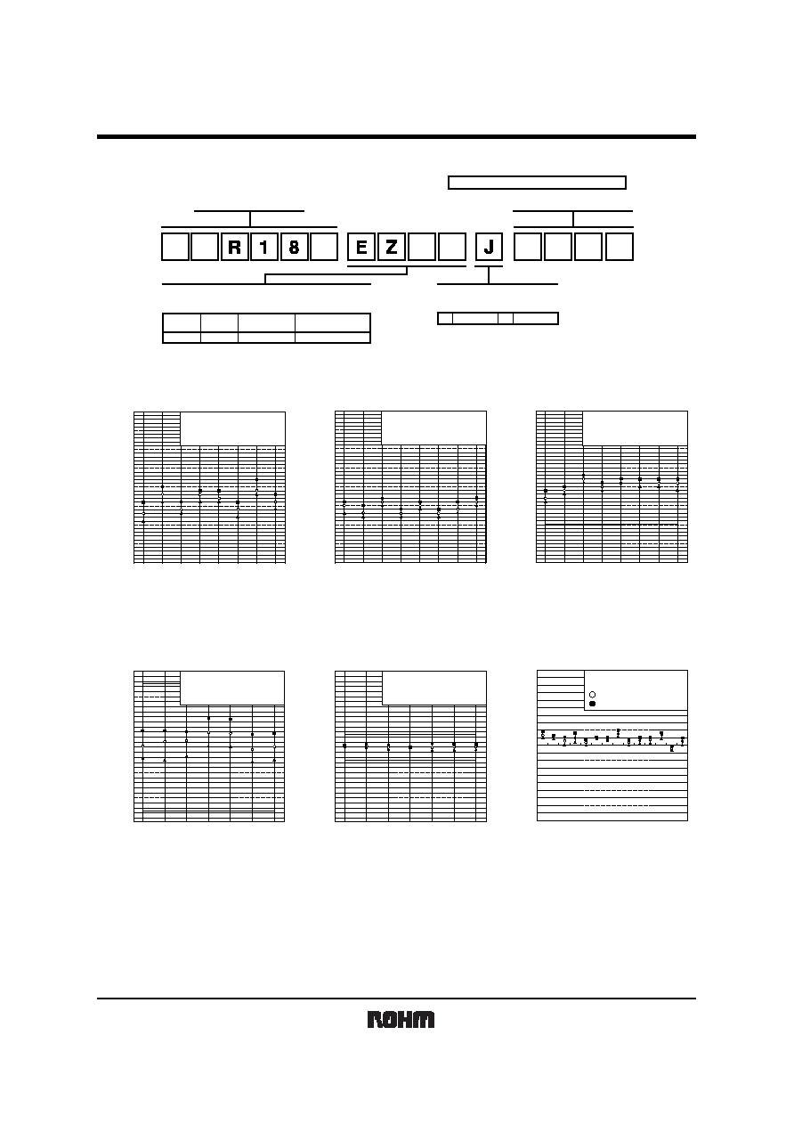
Makeup of the part number
KTR18
EZP
5,000
F
±
1%
±
5%
J
Part No.
Paper tape
Code
Packaging
Standard ordering
unit(pcs)
Packaging / Processing specifications
Resistance tolerance
Nominal resistance
Part No.
3-digit or 4-digit IEC coding system
K
T
P
Dimensions
RESISTANCE
(
)
Fig.2 Dimensions (length)
3.00
3.05
3.10
3.15
3.20
3.25
3.30
3.35
3.40
LENGTH
(mm)
JIS C 5201-1 4.4
SAMPLE SIZE : n
=
20pcs
MICROMETER
10
1
100
1k
10k 100k 1M 10M
1.40
1.45
1.50
1.55
1.60
1.65
1.70
1.75
1.80
10
1
100
1k
10k 100k 1M 10M
RESISTANCE
(
)
Fig.3 Dimensions (width)
WIDTH
(mm)
JIS C 5201-1 4.4
SAMPLE SIZE : n
=
20pcs
MICROMETER
0.35
0.40
0.45
0.50
0.55
0.60
0.65
0.70
0.75
10
1
100
1k
10k 100k 1M 10M
RESISTANCE
(
)
Fig.4 Dimensions (thickness)
THICKNESS
(mm)
JIS C 5201-1 4.4
SAMPLE SIZE : n
=
20pcs
MICROMETER
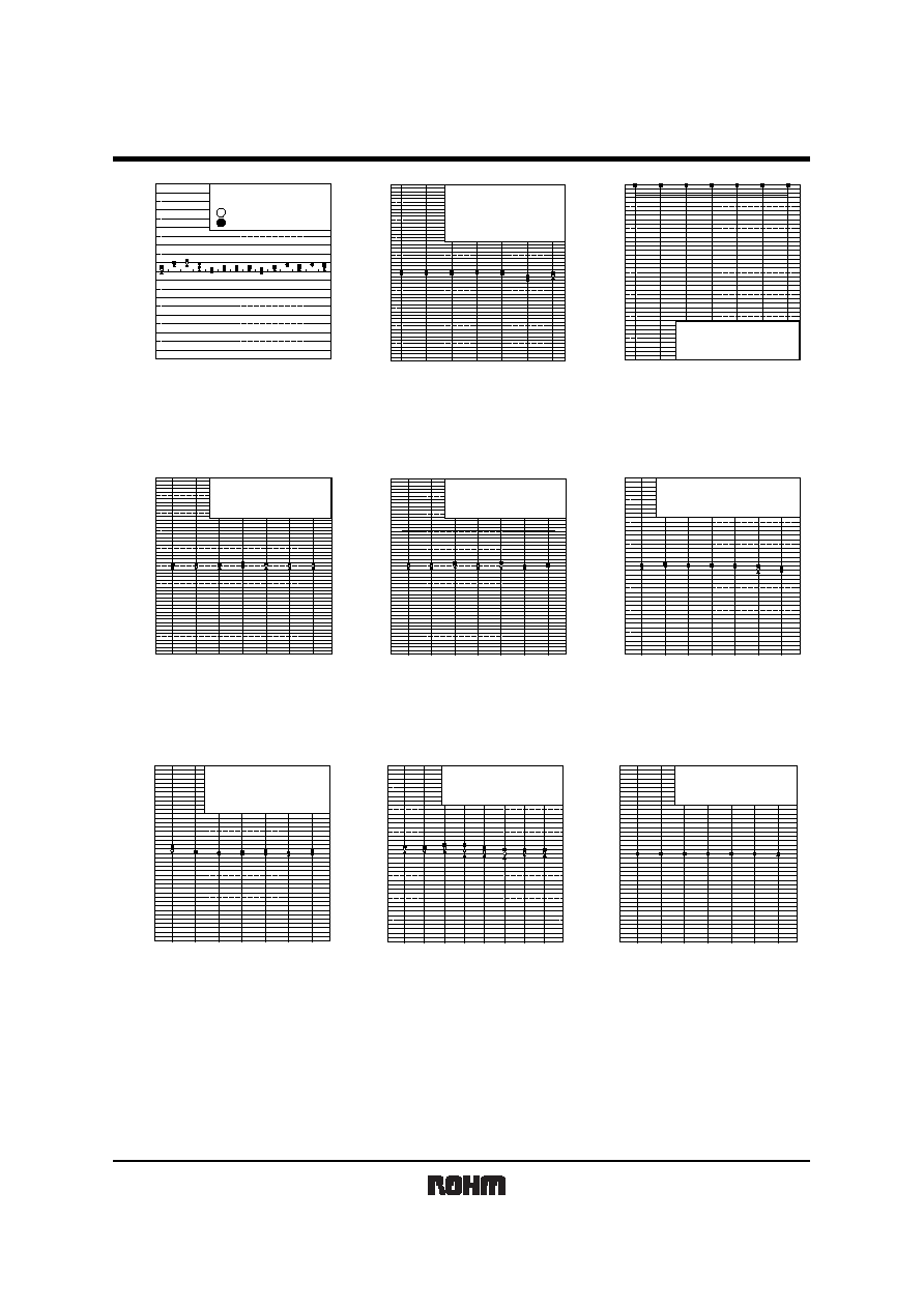
Electrical characteristics
-
6.0
-
4.0
-
2.0
0.0
2.0
4.0
6.0
RESISTANCE
(
)
Fig.5 Resistance (J class)
DC RESISTANCE
(%)
JIS C 5201-1 4.5
SAMPLE SIZE : n
=
20pcs
20
∞
C 65%RH
10
100
1k
10k
100k
1M
10M
-
6.0
-
4.0
-
2.0
0.0
2.0
4.0
6.0
RESISTANCE
(
)
Fig.6 Resistance (F class)
DC RESISTANCE
(%)
JIS C 5201-1 4.5
SAMPLE SIZE : n
=
20pcs
20
∞
C 65%RH
10
100
1k
10k
100k
1M
10M
RESISTANCE
(
)
Fig.7 Variation resistance with
temperature (J class)
-
500
-
400
-
300
-
200
-
100
0
100
200
300
500
400
TEMPERATURE COEFFICIENT (ppm/
∞
C)
10
100
1k
10k
100k
1M
10M
JIS C 5201-1 SEC 4.8
SAMPLE SIZE : n
=
10pcs
25
∞
C /
-
55
∞
C
25
∞
C / 125
∞
C
KTR18
Resistors
5/6
-
500
-
400
-
300
-
200
-
100
0
100
200
300
500
400
RESISTANCE
(
)
Fig.8 Variation resistance with
temperature (F class)
TEMPERATURE COEFFICIENT (ppm/
∞
C)
10
100
1k
10k
100k
1M
10M
JIS C 5201-1 SEC 4.8
SAMPLE SIZE : n
=
10pcs
25
∞
C /
-
55
∞
C
25
∞
C / 125
∞
C
RESISTANCE
(
)
Fig.9 Overload
R/R
(%)
10
100
1k
10k
100k
1M
10M
JIS C 5201-1 4.13
SAMPLE SIZE : n
=
10pcs
RATED VOLTAGE
◊
2.5
TIMES : 2s
MAXIMUM OVERLOAD VOLTAGE : 800V
-
4.0
-
5.0
-
3.0
-
2.0
-
1.0
0.0
1.0
2.0
3.0
4.0
5.0
SOLDERD PERCENTAGE
(%)
100
1k
10k
100k
1M
RESISTANCE
(
)
Fig.10 Solderability
10
10M
JIS C 5201-1 4.17
SAMPLE SIZE : n
=
10pcs
SOLDERING CONDITION : 235
∞
C 2s
20
30
40
50
60
70
80
90
100
RESISTANCE
(
)
Fig.11 Resistance to soldering heat
R/R
(%)
JIS C 5201-1 SEC 4.18
SAMPLE SIZE : n
=
10pcs
SOLDERING CONDITION : 260
∞
C 10s
10
100
1k
10k 100k 1M
10M
-
2.5
-
2.0
-
1.5
-
1.0
-
0.5
0.0
0.5
1.0
1.5
2.5
2.0
RESISTANCE
(
)
Fig.12 Rapid change of temperature
R/R
(%)
JIS C 5201-1 SEC 4.19
SAMPLE SIZE : n
=
10pcs
-
55
∞
C / 125
∞
C 1000cyc
10
100
1k
10k 100k 1M
10M
-
2.5
-
2.0
-
1.5
-
1.0
-
0.5
0.0
0.5
1.0
1.5
2.5
2.0
-
4.0
-
3.0
-
2.0
-
1.0
0.0
1.0
2.0
3.0
4.0
RESISTANCE
(
)
Fig.13 Damp heat , Steady state
R/R
(%)
10
100
1k
10k 100k 1M
10M
JIS C 5201-1 SEC 4.24
SAMPLE SIZE : n
=
10pcs
40
∞
C 93%RH WITH NO LOAD 1,000h
-
4.0
-
3.0
-
2.0
-
1.0
0.0
1.0
2.0
3.0
4.0
R/R
(%)
100
1k
10k 100k 1M
RESISTANCE
(
)
Fig.14 Endurance (at70
∞
C)
10
10M
JIS C 5201-1 SEC 4.25.1
SAMPLE SIZE : n
=
10pcs
70
∞
C 1,000h
THE RATED VOLTAGE 1.5h on, 0.5h off
-
4.0
-
3.0
-
2.0
-
1.0
0.0
1.0
2.0
3.0
4.0
RESISTANCE
(
)
Fig.15 Endurance
R/R
(%)
10
1
100
1k 10k 100k 1M 10M
JIS C 5201-1 SEC 4.25.3
SAMPLE SIZE : n
=
10pcs
155
∞
C WITH NO LOAD 1,000h
-
2.0
-
1.5
-
1.0
-
0.5
0.0
0.5
1.0
1.5
2.0
RESISTANCE
(
)
Fig.16 Component solvent resistance
R/R
(%)
10
100
1k
10k 100k 1M
10M
JIS C 5201-1 SEC 4.29
SAMPLE SIZE : n
=
10pcs
IPA, 5min.