LD-001 Series
LED displays
Flat displays
LD-001 Series
The LD-001 series were designed in
response to the need for medium-sized, flat
displays. These are two-chip, flat displays
with high luminance.
!
!
!
!Features
1) 4.5 x 9.5 mm planar emission from two
chips connected in series.
2) High luminance, uniform emission.
3) Four colors : red, orange, yellow and
green.
!
!
!
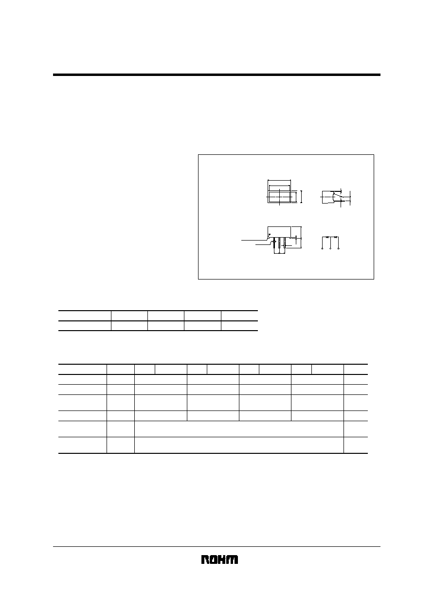
!External dimensions
(Units : mm)
R4
2
∞
(1.8)
0.3
0.6
Cathode mark
(2.5) (2.5)
5.0
±
0.5
5.6
±
0.1
0.6
-
0.1
-
0.1
+
0
+
0
10.7
9.5
±
0.1
4.5
±
0.1
5.7
Pin No.1
2
3
Max.0.8
2
3
Tolerances are
±
0.3 unless otherwise noted:
Pin No.1
!
!
!
!Selection guide
Red
LD-001VR
Orange
LD-001DU
Yellow
LD-001YY
Green
LD-001MG
Emitting color
Type
Order-based production.
!
!
!
!Absolute maximum ratings
(Ta = 25
∞C)
Parameter
Symbol
Red
Unit
LD-001VR Orange LD-001DU Yellow
LD-001YY
Green LD-001MG
mW
mA
mA
V
∞
C
∞
C
P
D
I
F
I
FP
V
R
Topr
Tstg
Power dissipation
Forward current
Peak forward
current
Reverse voltage
Operating
temperature
Storage
temperature
120
20
60
60
60
60
3
120
20
3
120
20
3
150
25
3
-
25~
+
75
-
30~
+
85
Pulse width 1ms duty 1 / 5

LD-001 Series
LED displays
!
!
!
!Electrical and optical characteristics
(Ta = 25
∞C)
Parameter
Symbol
Red
Orange
Yellow
Green
Unit
Conditions
Min.
Typ. Max. Min.
Typ. Max.
2.8
V
µ
A
nm
nm
2.0
2.8
2.0
650
40
10
610
40
10
-
-
-
-
-
-
-
-
-
-
-
-
-
-
Min.
Typ. Max.
2.8
2.1
585
40
10
-
-
-
-
-
-
-
Min.
Typ. Max.
2.8
2.1
563
40
10
-
-
-
-
-
-
-
I
F
=
10mA
V
R
=
3V
I
F
=
10mA
I
F
=
10mA
V
F
I
R
P
Forward voltage
Reverse current
Peak wavelength
Spectral line half
width
Electrical and optical values are guaranteed values per element.
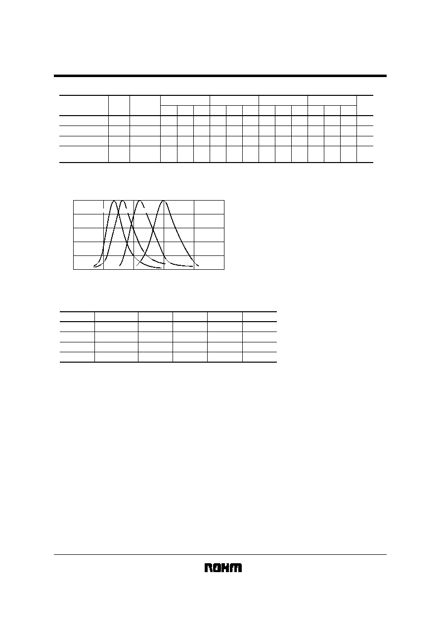
!Luminous intensity vs. wavelength
1.0
0.8
0.6
0.4
0.2
0
500
550
600
650
700
750
Axial Luminous Intensity
Wavelength :
P
(nm)
Green
Yellow
Orange
Red
!
!
!
!Luminous intensity
Color
Orange
Yellow
Green
Type
LD-001VR
LD-001DU
LD-001YY
LD-001MG
Red
Min.
2.2
2.2
1.4
3.6
Typ.
6.3
6.3
4.0
10
Max.
-
-
-
-
Unit
mcd
mcd
mcd
mcd
Note 1: Measured at I
F
= 10mA
Note 2: Current passes through 2 elements in series.
!
!
!
!Operation notes
When forming leads, the bend should be at least 2mm from the base of the package. Solder after forming the leads, and
ensure that the inside of the LED is not subjected to mechanical stress while it is hot.

