RB471E
Diodes
Schottky barrier diode
RB471E
Applications
Low current rectification
For switching power supplies
Features
1) Small surface mounting dual element parallel type.
(SMD5)
2) Low V
F
.( V
F
=0.45V Typ. at 100mA )
3) High reliability.
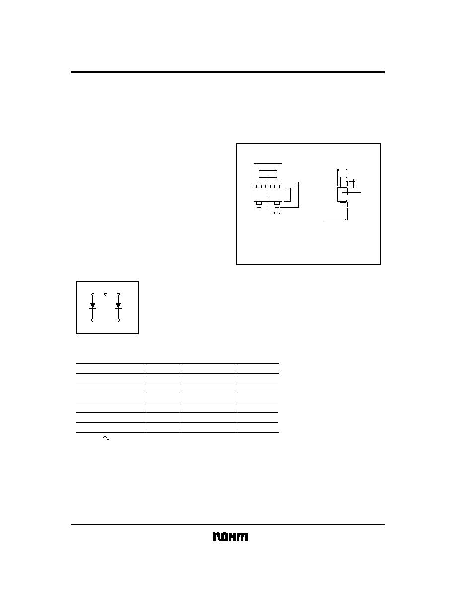
Construction
Silicon epitaxial planar
Circuit
External dimensions (Units : mm)
ROHM : SMD5
EIAJ : SC
-
74A
JEDEC :
-
0~0.1
0.3~0.6
2.8
±
0.2
1.6
1.1
0.8
±
0.1
0.15
0.3
2.9
±
0.2
1.9
±
0.2
0.95 0.95
+
0.2
-
0.1
-
0.1
+
0.2
+
0.1
-
0.06
+
0.1
-
0.05
D 3 G
(All leads have same dimentions)
Absolute maximum ratings (Ta = 25
∞
C)
Parameter
Symbol
Limits
Unit
Peak reverse voltage
V
RM
40
V
DC reverse voltage
V
R
40
V
Mean rectifying current
I
O
0.1
A
Peak forward surge current
I
FSM
1
A
Junction temperature
125
∞
C
Storage temperature
∞
C
T
j
T
stg
-
40
~
+
125
60 Hz for 1
RB471E
Diodes
Electrical characteristics (Ta = 25
∞
C)
Note) ESD sensitive product handling required.
Parameter
Symbol
Min.
Typ.
Max.
Unit
Conditions
Forward voltage
V
F1
-
0.28
0.34
V
I
F
=
10mA
V
F2
-
0.45
0.55
V
I
F
=
100mA
Reverse current
I
R
-
1
30
µ
A
V
R
=
10V
Capacitance between terminals
-
6.0
-
pF
V
R
=
10V, f
=
1MHz
C
T
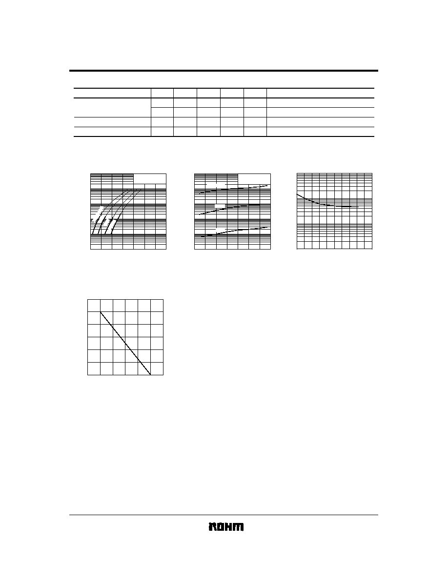
Electrical characteristic curves (Ta = 25
∞
C)
0
1
100m
10m
1m
100
µ
10
µ
0.1
0.2
0.3
0.4
0.5
0.6
0.7
Ta
=
125
∞
C
75
∞
C
25
∞
C
-
25
∞
C
pulse measurement
Typ.
FORWARD CURRENT : I
F
(
A)
FORWARD VOLTAGE : V
F
(V)
Fig. 1 Forward characteristics
0
5
10
15
20
25
30
35
10m
1m
100
µ
10
µ
1
µ
0.1
µ
pulse measurement
Typ.
REVERSE : CURRENT : I
R
(
A)
REVERSE VOLTAGE : V
R
(V)
Fig. 2 Reverse characteristics
Ta
=
125
∞
C
75
∞
C
25
∞
C
0
5
10
15
20
25
0.1
1
10
100
CAPACITANCE BETWEEN TERMINALS : C
T
(
pF)
REVERSE VOLTAGE : V
R
(V)
Fig. 3 Capacitance between
terminals characteristics
0
0
20
40
60
80
100
25
50
75
100
125
Io CURRENT (%)
AMBIENT TEMPERATURE : Ta (
∞
C)
Fig 4. Derating curve
(mounting on glass epoxy PCBs)