Äîêóìåíòàöèÿ è îïèñàíèÿ www.docs.chipfind.ru

RCM1990U-A
Liquid crystal displays
1/8
16
×16 dots large-sized
liquid crystal display unit
RCM1990U-A
Thanks to the high contrast and wide viewing angle of the RCM1990U-A, which is provided by its unique design
technology, this module brings forth new applications in brand new LCD fields. ROHM large-sized LCD units are perfect
displays for information or sign boards. As a media for informational display, large-sized LCD units must possess high
visibility, wide viewing angles, and other such superior qualities. ROHM large-sized LCDs boast an excellent track record
and possess guaranteed functionality for assured satisfaction in a variety of situations.
Applications
Public displays such as airport displays, train station displays, information boards, and billboards.
Features
1) Wide viewing angle, high contrast, and fast response.
2) Compact and light weight for easy assembly.
3) Low power consumption.
External dimensions
(Unit : mm)
2.00Max.
20.75Min.
23.75Min.
33.75Min.
36.75Min.
35.00
±
0.50
46.00
±
0.50
C2.0
23.00
±
0.30
57.50
±
0.30
(3.50)
(15.00)
(8.00)
4.00
±
0.30
27.00
±
0.30
(4.00)
2.00Max.
54.00Min.
0.3Max.
54.00Min.
(64.70)
(40.5)
(R3.20)
2.50
±
0.30
1.00
±
0.30
2.70
±
0.50
2.65
±
0.30
1.10
±
0.10
1.10
±
0.10
56.00
±
0.30
1.0Max.
50.97
±
0.30
2.515
±
0.30
61.00
±
0.30
CN 2
8
1
8
1
CN 1

RCM1990U-A
Liquid crystal displays
2/8
Block diagram
COM.2
COM.1
OUTPUT
FLM
VO
V
DD
M
CL1
CL2
D
O
GND
INPUT
FLM
VO
V
DD
M
CL1
CL2
DI
GND
LCD
COM
Generator circuit
64 output
driver IC
64 output
driver IC
Pin functions
Upper board
Input (CN3)
Pin No.
1
2
3
4
5
6
7
8
Frame start signal
Liquid crystal drive power supply
5 volts
AC conversion signal for liquid crystal drive output
Data latch signal, displays at rise / fall edge
Shift register shift signal, reads data at rise / fall
Display data signal (1 : On, 0 : Off)
Ground potential
Function
IN/OUT
IN
-
-
IN
IN
IN
IN
-
Symbol
FLM
VO
V
DD
M
CL1
CL2
DI
GND
Output (CN4)
Pin No.
1
2
3
4
5
6
7
8
Frame start signal
Liquid crystal drive power supply
5 Volts
AC conversion signal
Data latch signal
Shift register shift signal
Display data signal
Ground potential
Function
IN/OUT
OUT
-
-
OUT
OUT
OUT
OUT
-
Symbol
FLM
VO
V
DD
M
CL1
CL2
DI
GND

RCM1990U-A
Liquid crystal displays
3/8
Absolute maximum ratings
(Ta
=25°C)
Input voltage
Operating temperature
Storage temperature
Limits
-
0.3 to
+
7.0
-
0.3 to
+
7.0
-
0.3 to V
DD
+
0.3
0 to
+
50
-
10 to
+
60
Symbol
V
DD
V
DD
-V
EE
V
IN
T
opr
T
stg
Unit
V
V
V
°
C
°
C
Logic circuit
LCD drive
Power supply
voltage
Parameter
Electrical characteristics
(Ta
=25°C, V
DD
=5.0V±0.25V)
High level input voltage
Low level input voltage
High level output voltage
Low level output voltage
Recommended LCD drive voltage
Current dissipation
Parameter
I
OH
=-
0.4mA
I
OH
=+
0.4mA
Ta
=
25
°
C
f
CL
=
1MHz, f
M
=
70Hz
Conditions
Unit
V
V
V
V
V
mA
Max.
-
1.5
-
0.4
-
3.0
Typ.
-
-
-
-
5.0
1.0
Min.
3.5
-
4.6
-
-
-
V
IH
V
IL
V
OH
V
OL
V
LCD
I
DD
Symbol
AC characteristics
(Ta
=25°C, V
DD
=5.0)
Shift frequency
High level lock width
Low level lock width
Data setup time
Clock setup time 1
Clock setup time 2
Data hold time
FLM setup time
FLM hold time
Clock rise / fall time
Output delay time
AC conversion signal
Parameter
f
CL
t
CWH
t
CWL
t
SU
t
SL
t
LS
t
DH
t
FDS
t
FDH
t
ct
t
pd
f
M
Symbol
CL2
CL1, CL2
CL2
DI
CL2
CL1
DI
FLM
FLM
CL1, CL2
DO
M
-
470
470
120
220
220
120
120
120
-
-
-
Min.
-
-
-
-
-
-
-
-
-
-
-
70
Typ.
1
-
-
-
-
-
-
-
-
50
250
-
Max.
MHz
ns
ns
ns
ns
ns
ns
ns
ns
ns
ns
Hz
Unit
Applicable terminal

RCM1990U-A
Liquid crystal displays
4/8
Timing characteristics
V
IH
V
IH
V
IH
V
IL
V
OH
V
OL
V
IH
V
IH
V
IL
V
IL
CL2
DI
DO
CL1
FLM
t
CWL
t
ct
t
SU
t
SL
t
CWH
t
LS
t
ct
t
CWH
t
ct
t
pd
t
ct
t
DH
t
FDS
t
FDH
Optical characteristics
(Ta
=25°C)
Response speed
Tr
-
Symbol
Min.
65
Typ.
130
Td
-
400
800
Viewing angle
0
-
60
(Note 3)
K
3
Front-back
Right-left
90
-
270
Contrast ratio
25
Temperature (
°
C)
0
25
25
1
No.
Parameter
2
3
Max.
ms
(Note 2)
deg
Unit
Note
25
0
25
K
20
40
-
-
-
45
150
100
300
=
180
°
=
10
°
(Note 1) Drive waveform
Static drive
V
OP
0
-
V
OP
1 / f
-
1 / 2V
OP
1 / 2V
OP
f = Frequency
(Note 2) Definition of response speed
OFF
ON
I
0.11
0.91
T
T
d
I
ON
I
OFF
T
r
RCM1990U-A
Liquid crystal displays
5/8
Tr : Time for segment to darken 90% after selective waveform switches to non-selective waveform.
=180°, =10°
Td : Time for segment to darken 90% after selective waveform switches to non-selective waveform.
=180°, =10°
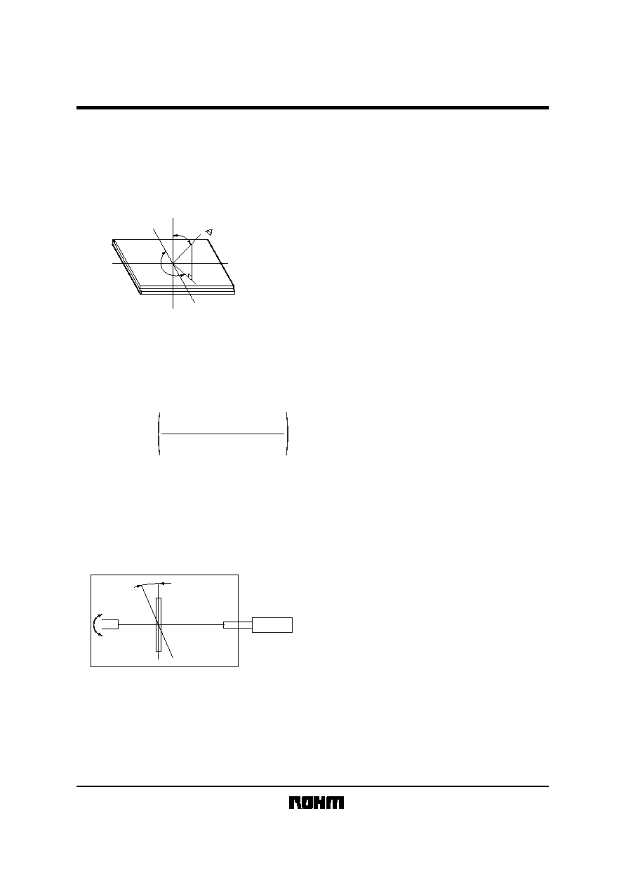
(Note 3) Definition of viewing angle (
, )
Z
X'(
=
270
°
)
Y'(
=
180
°
)
X(
=
90
°
)
Y(
=
0
°
)
Z'
LCD
Observer
(1)
: Angle subtended by the Y-Y'-axis and the observer's position projected onto the XY-plane.
(2)
: Angle subtended by observer and the normal Z-Z'axis. (X-axis and Y-axis are positive)
(3) Maximum viewing angle : The direction with highest contrast expressed at the time axis (refer to above table).
(Note 4) Definition of contrast ratio
<Definition>
Contrast ratio
=
Luminance during application
of non-selective waveform
Luminance during application
of selective waveform
n
Except, n
=1 with positive display and n=-1 with negative display.
< Measurement conditions >
Drive conditions : As per specifications
Viewing angle :
=180°, =10°
(Note 5) Principles of optical measuring equipment
LCD-5100
Illumination
Specimen
Photometry
Characteristic
measuring
device
Constant temperature chamber
Document Outline