Äîêóìåíòàöèÿ è îïèñàíèÿ www.docs.chipfind.ru
RPM5500 series
Photo Link Module
1/7
IR Receiver Module
RPM5500 series
RPM5500 series are remote control receiver modules. Small-sized, light-weight, and low current consumption modules
have been achieved by using resin mold.
Applications
All household electric appliances such as TV, DVD, air conditioner and audio equipment.
Features
1) Small size, SMD type.
2) Low current consumption. (0.95mA Typ.)
3) High ripple rejection.
4) Top view package type & Side view package type.
RPM5500 series
Sub carrier frequency
TOP VIEW
36.7kHz
RPM5537-H12
RPM5538-H12
RPM5540-H12
SIDE VIEW
RPM5537-H14
RPM5538-H14
RPM5540-H14
37.9kHz
40.0kHz
Absolute maximum ratings (Ta = 25
°
C)
Parameter
Symbol
Limits
Unit
Supply Voltage
V
CC
6.3
-
10 to
+
75
-
30 to
+
100
V
mA
2.0
Operating temperature
Storage temperature
Output Current
Topr
Tstg
Io
°
C
°
C
Recommended operating conditions (Ta = 25
°
C)
Parameter
Symbol
Min.
Typ.
Max.
Unit
Supply Voltage
V
CC
5.0
V
4.5
5.5
RPM5500 series
Photo Link Module
2/7
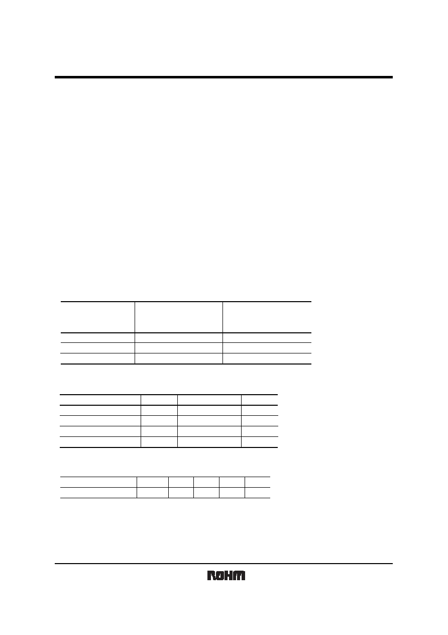
Block diagram
Comparator
LIMITER
AMP
22k
V
CC
R
OUT
GND
I / V
BPF
Demodulator
and integrator
Terminal description
Pin name
Pin No.
Function
1
V
CC
POWER SUPPLY
GROUND
GROUND
GROUND
OUTPUT TERMINAL
GROUND
GROUND
2
3
4
5
6
7
GND
GND
GND
R
OUT
GND
GND
Electrical, Optical characteristics (Unless otherwise noted, Ta = 25
°
C V
CC
=5V)
1 600/600
µ
s burst wave is transmitted by standard transmitter. However, it must be measured after the initial transmission pulse is 10 pulse.
2 It is an angle when the linear arrival distance become half.
3 Three types of frequencies : 36.7, 37.9, 40kHz.
Parameter
Symbol
Min.
Typ.
Max.
Unit
Conditions
Consumption Current
I
CC
V
H
L
V
L
T
ON
T
OFF
fo
0.95
mA
No outside light, No signal input
Outer light condition Ee
<
10 (Ix)
Isink 200
µ
A
Effective Distance
High Level Output Voltage
Low Level Output Voltage
ON Pulse Width
OFF Pulse Width
Center frequency
Vertical half angle
12
-
-
600
1.5
m
-
V
-
V
µ
s
0.5
800
Horizontal half angle
1/2
1/2
600
3
1
1
1
Outer light condition Ee
<
10 (Ix)
1
Outer light condition Ee
<
10 (Ix)
1
2
2
-
7
400
4.5
-
400
-
-
-
38
42
µ
s
800
kHz
-
-
deg
deg
-
=
<
Measurement Conditions
(1) Transmit signal
600
µ
s
600
µ
s
Fig.1 Transmit signal
Carrier frequency=fo, Duty=50%
RPM5500 series
Photo Link Module
3/7
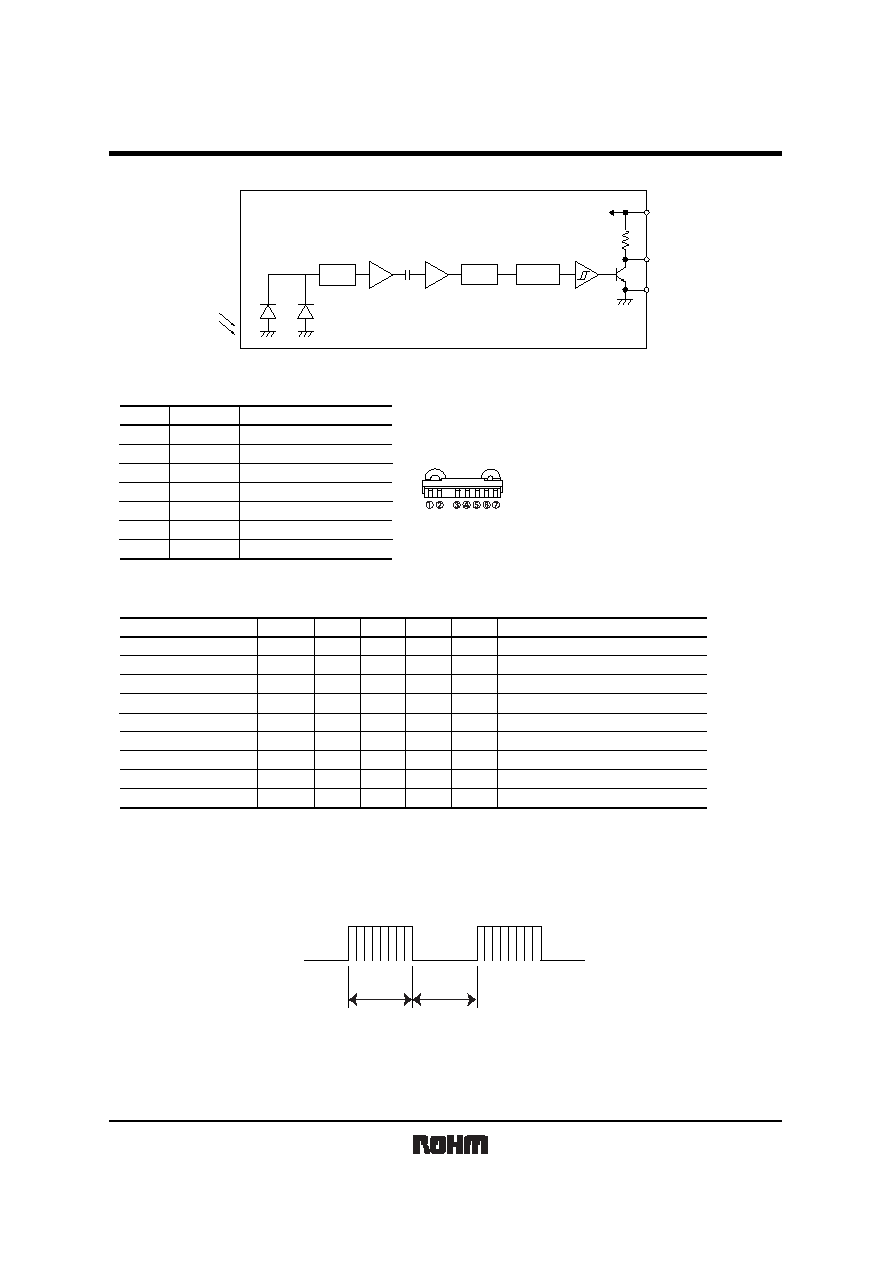
(2) Standard transmitter
Fig.2 Measurement of standard transmitter proofreading
Standard transmitter
R
20cm
io=V
OUT
/ R
peak=940nm
=40nm
RPM-302B
V
OUT
When standard transmitter output the signal at Fig.1 standard photodiode output become io=5
µ
Ap-p under the
measurement condition Fig.2.
(The radiant intensity of standard transmitter : 50mW / sr)
RPM-302B : standard photodiode has short current Isc=27
µ
A at E=1000(lx)
(using CIE standard light source A)
(3) Measurement effective distance, horizontal & vertical half angle
Fig.3 Measurement condition for effective distance
RPM5500 series
Light detector face
illuminance : Ee
Effective distance : L
(
; Indicates horizontal and vertical directions)
Standard transmitter
Effective distance L : Effective distance at
=0
°
Fig.3
Horizontal & vertical half angle
: The angle which effective distance became 50% of L.
RPM5500 series
Photo Link Module
4/7
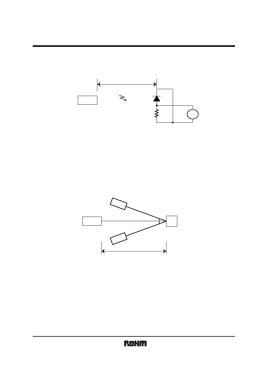
(4) Output signal
600
µ
s
T
ON
T
OFF
V
CC
GND
1/2 V
CC
V
H
V
L
600
µ
s
Fig.4
Carrier frequency=f
0
Carrier Duty=50%
Transmit signal
Output signal
(5) Measurement circuit for the output voltage and the consumption current
Fig.5
V
CC
V
H
, V
L
V
CC
I
CC
R
OUT
GND
A
V
RPM5500
RPM5500 series
Photo Link Module
5/7
Notes
(1) All characteristics of the receiver in this specification are specified by supplying burst wave form (Fig.1) with ROHM
standard transmitter (Fig.2 ).
If in case of other burst wave form will be used, please check these spec. Carefully under the evaluations.
(2) When the receiver will be used as the wire-less remote controller, please use the signal method the signal format
which refer to "Measures to prevent mulfunctioning of IR remote-controlled electric home appliances". (Published July
1987 by Association of Electric Home Appliances)
If using other signal method, signal format, (ex: signal format which not including the leader signal) the receiver might
have chances to miss-function.
(3) Please set up transmitter's carrier frequency as same as the receiver's f
0
frequency. Otherwise error might be
occurred.
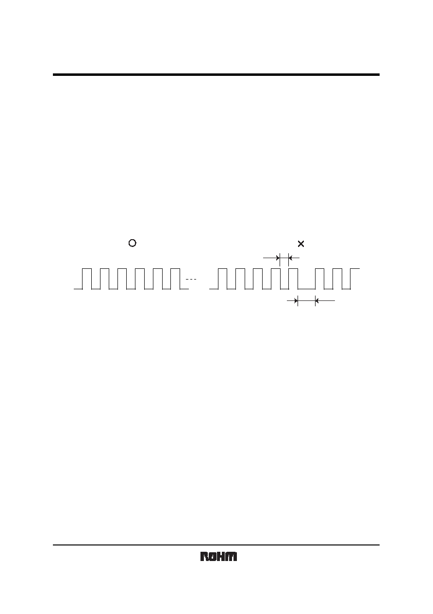
(4) If transmission signal has non-continues carrier, error might be occurred. Continuous carrier is necessary.
T1
T2
T1
T2
(5) The receiver was designed to use as in-door use only.
Therefore, please understand that the receiver cannot cover all characteristics, in case of using it out-door.
(6) Noise environment (Light noise from inverter Lamp, and other kind of Lamps, Power ripple, electromagnetic noise from
power circuit, and etc) may cause a reduced effective distance.
(7) The receiver may not work properly if receiving signal judgement is done by single pulse due to the
surrounding / environmental noises.
To prevent such misjudgement, please make sure that the receiver is set up to work only when receiving
series of coded signal.
(8) Emitting unit (remote control transmitter) has to be considered about its emitting device function, characteristics and
characteristics of the receiver.
(9) Please connect `Holder' on to the `Ground (GND)' of PCB. If the holder is not connected to the GND, there is a
possibility of worsening the characteristics of product.
(10) Do not supply unnecessary stress to lead.
(11) Please pay careful attention to the lens.
It might have a chance to miss-function when the lens get dust or dirty. And also please do not touch the lens.
(12) In order to prevent products from ESD, human body and solder iron, etc. are required to be grounded.
Document Outline