
0.35
µ
µ
µ
µ
m SIGMA-DELTA VOICE ADC
BW0406XB
1
GENERAL DESCRIPTION
The BW0406XB is Sigma-Delta ADC for speech and telephony applications. The product contains both digital IIR
and FIR filter. The normal output channels have with 70dB signal to distortion ratio. The output of this device is
14bit linear. An on-chip voltage reference circuit is included to allow the single supply operation.
FEATURES
-- Single chip voice line ADC
-- Oversampled Sigma Delta modulator
-- Output format : linear 14bit
- When serial interface mode, the 14bit linear data has 16bit format with two don't care bits from LSB
- 2's complement format
-- 256X Oversampling
-- On chip Decimation Filter
-- Single ended Input
-- Sampling Rate of 8~11KHz
-- On chip voltage reference circuitry
-- Single +3.3V Power Supply
-- 2Vpp Input signal swing
-- Power Consumption
- Operating Mode : 6mW Typ(3.3V)
- Powerdown Mode : 33mW Typ(3.3V)
TYPICAL APPLICATIONS
-- Speech Processing (Recognition, Synthesis, Compression etc.)
-- Telephony
-- Modem

0.35
µ
µ
µ
µ
m SIGMA-DELTA VOICE ADC
BW0406XB
3
CORE PIN DESCRIPTION
Name
I/O Type
I/O Pad
Pin Description
VDDA
AP
vdda
Analog Power (+3.3V)
VSSA
AG
vssa
Analog Ground (0.0V)
REFH
AP
piar50_bb
Analog Reference Power(+3.3V)
REFL
AG
piar50_bb
Analog Reference Ground (0.0V)
AMODIN
AI
piar50_bb
ADC Analog input
VREFOUT
AO
poar50_bb
Vref output
AINFB
AI
piar50_bb
Analog Input Gain control
PWD
DI
picc_bb
Power Down (High active)
RST
DI
picc_bb
Digital Reset (High active)
X256FS
DI
picc_bb
256*Sampling Freq.(FS) Clock
SYNC
DO
pot2_bb
Sampling Freq.(FS) Clock
BCK
DO
pot2_bb
Bit Clock
SDOUT
DO
pot2_bb
Serial Data Output
PDOUT[13:0]
DO
pot2_bb
Parallel Data Output [14bit]
VSSD
DG
vssd
Digital Ground
VDDD
DP
vddd
Digital Power Supply
NOTES:
1.
The Power pin(VDDA,VDDD) must be connected by DIODE_SLOT2.
2.
The
Ground
pin
(VSSA,
VSSD)
must
be
connected
bye
DIODE_SLOT2.
I/O Type Abbr.
-- AI: Analog Input
-- DI: Digital Input
-- AO: Analog Output
-- DO: Digital Output
-- AB: Analog Bidirectional
-- DB: Digital Bidirectional
-- AP: Analog Power
-- DP: Digital Power
-- AG: Analog Ground
-- DG: Digital Ground
0.35
µ
µ
µ
µ
m SIGMA-DELTA VOICE ADC
BW0406XB
5
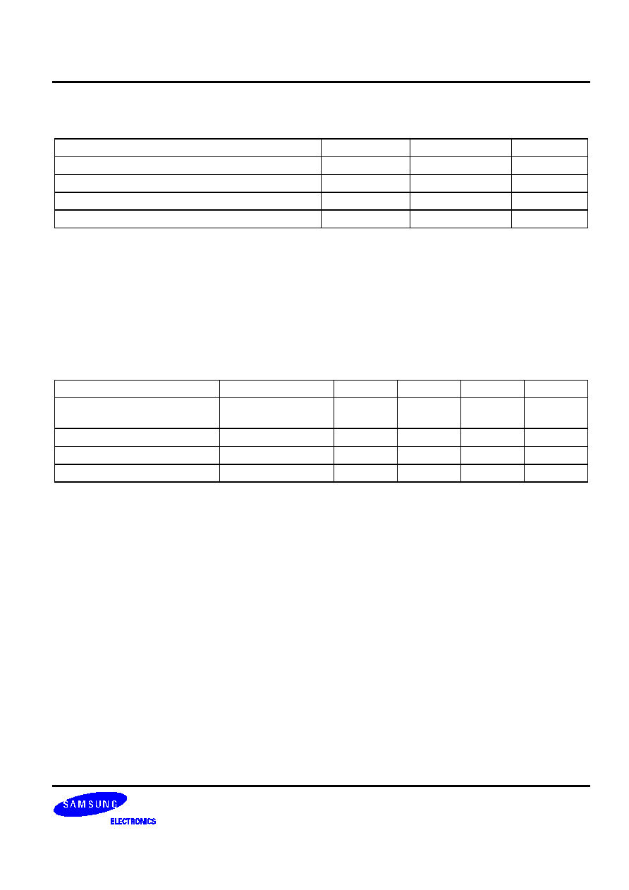
ABSOLUTE MAXIMUM RATINGS
Characteristic
Symbol
Value
Unit
Supply Voltage
VDDD
-0.3 to 3.8
V
Digital Input Voltage
D
IN
-0.3 to 3.8
V
Storage Temperature Range
Tstg
-40 to 125
∞
C
Operating Temperature Range
Topr
0 to 70
∞
C
NOTES:
1.
ABSOLUTE
MAXIMUM
RATING
specifies
the
values
beyond
which
the
device
may
be
damaged
permanently.
Exposure
to
ABSOLUTE
MAXIMUM
RATING
conditions
for
extended
periods
may
affect
reliability.
Each
condition
value
is
applied
with
the
other
values
kept
within
the
following
operating
conditions
and
function
operations
under
any
of
these
conditions
is
not
implied.
2.
All
voltages
are
measured
with
respect
to
VSS(VSSA
or
VSSD)
unless
otherwise
specified.
RECOMMENDED OPERATING CONDITIONS
Characteristics
Symbol
Min
Typ
Max
Unit
Supply Voltage
VDDA
∑
VSSA
VDDD
∑
VSSD
3.15
3.3
3.45
V
Supply Voltage Difference
VDDA
∑
VDDD
0.1
0.0
0.1
V
Digital Input Voltage Range
2.7
3.3
3.6
V
Analog Input Voltage Range
≠
2
≠
Vpp
NOTE: It
is
strongly
recommended
that
all
the
supply
pins
(VDDA,
VDDD)
be
powered
from
the
same
source
to
avoid
power
latch
up.

