Revision 1.0
January 2005
K1B6416B6C
- 1 -
UtRAM
Document Title
4Mx16 bit Synchronous Burst Uni-Transistor Random Access Memory
The attached datasheets are provided by SAMSUNG Electronics. SAMSUNG Electronics CO., LTD. reserve the right to change the specifications and
products. SAMSUNG Electronics will answer to your questions about device. If you have any questions, please contact the SAMSUNG branch offices.
Revision History
Revision No.
0.0
0.1
0.2
0.3
0.4
1.0
Remark
Advance
Advance
Advance
Preliminary
Preliminary
Final
History
Initial Draft
- Design target
Revised
- Deleted Deep Power Down Mode support
Revised
- Changed product code from K1B6416B7C into K1B6416B6C
Revised
- Filled out Package type(54ball FBGA 6.0mm x 8.0mm)
- Changed Hi-Z parameters(tCHZ, tOHZ, tBHZ, tWZ) from Max.7ns
into Max.12ns and changed tHZ from Max.10ns into Max.12ns
- Updated "Fig.17 TIMING WAVEFORM OF WRITE CYCLE(1)" in
page 23
- Added comment on standby current(I
SB1
) measure condition as
"Standby mode is supposed to be set up after at least one active
operation after power up. I
SB1
is measured after 60ms from the time
when standby mode is set up."
- Added comment on restriction of the transition between Asynchro-
nous Write operation and Fully Synchronous bus operation(Page
10,11)
- Filled out I
SB1
value, I
SBP
value and I
CC2
value in Table 17(DC AND
OPERATING CHARACTERISTICS)
- Added Synchronous Operating Current(I
CC3
, Max.40mA)
- Added tCSHP(A)(CS high pulse width) parameter as Min.10ns in the
ASYNCHRONOUS AC CHARACTERISTICS
Revised
- Changed I
SB1
(< 40
�
C) and I
SBP
(3/4 block, < 40
�
C) from 100
�
A into
120
�
A
- Changed I
SBP
(1/2 block and 1/4 block, < 40
�
C) from 95
�
A into 115
�
A
Finalized
Draft Date
March 11, 2004
April 19, 2004
May 10, 2004
September 1, 2004
October 12, 2004
January 20, 2005

Revision 1.0
January 2005
K1B6416B6C
- 2 -
UtRAM
4M x 16 bit Synchronous Burst Uni-Transistor CMOS RAM
FEATURES
�
Process Technology: CMOS
�
Organization: 4M x16 bit
�
Power Supply Voltage: 1.7~2.0V
�
Three State Outputs
�
Supports MRS (Mode Register Set)
�
MRS control - MRS Pin Control
�
Supports Power Saving modes - Partial Array Refresh mode
Internal TCSR
�
Supports Driver Strength Optimization for system environment
power saving.
�
Supports Asynchronous 4-Page Read and Asynchronous Write
Operation
�
Supports Synchronous Burst Read and Asynchronous Write
Operation(Address Latch Type and Low ADV Type)
�
Supports Synchronous Burst Read and Synchronous Burst
Write Operation
�
Synchronous Burst(Read/Write) Operation
- Supports 4 word / 8 word / 16 word and Full Page(256 word)
burst
- Supports Linear Burst type & Interleave Burst type
- Latency support : Latency 5 @ 66MHz(tCD 10ns)
Latency 4 @ 54MHz(tCD 10ns)
- Supports Burst Read Suspend in No Clock toggling
- Supports Burst Write Data Masking by /UB & /LB pin control
- Supports WAIT pin function for indicating data availability.
�
Max. Burst Clock Frequency : 66MHz
�
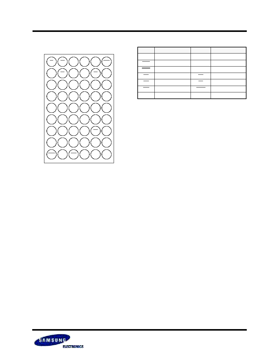
Package Type : 54 ball FBGA 6.0mm x 8.0mm
SAMSUNG ELECTRONICS CO., LTD. reserves the right to change products and specifications without notice
.
GENERAL DESCRIPTION
The world is moving into the mobile multi-media era and there-
fore the mobile handsets need much bigger memory capacity to
handle the multi-media data.
SAMSUNG's UtRAM products are designed to meet all the
request from the various customers who want to cope with the
fast growing mobile market.
UtRAM is the perfect solution for the mobile market with its low
cost, high density and high performance feature.
K1B6416B6C is fabricated by SAMSUNG
s advanced CMOS
technology using one transistor memory cell.
The device supports the traditional SRAM like asynchronous
bus operation(asynchronous page read and asynchronous
write), the NOR flash like synchronous bus operation(synchro-
nous burst read and asynchronous write) and the fully synchro-
nous bus operation(synchronous burst read and synchronous
burst write).
These three bus operation modes are defined through the mode
register setting.
The device also supports the special features for the standby
power saving. Those are the Partial Array Refresh(PAR) mode
and internal Temperature Compensated Self Refresh(TCSR)
mode.
The optimization of output driver strength is possible through the
mode register setting to adjust for the different data loadings.
Through this driver strength optimization, the device can mini-
mize the noise generated on the data bus during read operation.
Table 1. PRODUCT FAMILY
Product Family
Operating Temp.
Vcc Range
Clock
Freq.(Max)
Async.
Speed(tAA)
Current Consumption
Standby(Max)
(I
SB1
, <40
�
C)
Standby(Max)
(I
SB1
, <85
�
C)
Operating
(I
CC2
, I
CC3
, Max.)
K1B6416B6C-I Industrial(-40~85
�
C)
1.7~2.0V
66MHz
70ns
120
�
A
180
�
A
40mA
Revision 1.0
January 2005
K1B6416B6C
- 4 -
UtRAM
CONTENTS
Revision History
Features and General Description
Pin Description
Power Up Sequence
Functional Description
Mode Register Setting Operation
Mode Register Setting Timing
Asynchronous Operation
Asynchronous 4 Page Read Operation
Asynchronous Write Operation
Asynchronous Write Operation in Synchronous Mode
Synchronous Burst Operation
Synchronous Burst Read Operation
Synchronous Burst Write Operation
Synchronous Burst Operation Terminology
Clock
Latency Count
Burst Length
Burst Stop
WAIT Control
Burst Type
Low Power Features
Internal TCSR
Driver Strength Optimization
Partial Array Refresh(PAR) Mode
Product List
Absolute Maximum Ratings
Recommended DC Operating Conditions
Capacitance
DC and Operating Characteristics
Asynchronous AC Characteristics
Asynchronous Timing Waveforms
Synchronous AC Characteristics
Synchronous Timing Waveforms
Transition Timing Waveforms
Package Dimension
1
2
3
8
9
11
12
13
13
13
13
13
13
13
14
14
14
14
14
15
15
17
17
17
17
18
18
18
19
18
20
21
30
31
40
46
Page
Revision 1.0
January 2005
K1B6416B6C
- 5 -
UtRAM
LIST of TABLES
Table 1. Product Family
Table 2. Pin Description
Table 3. Asynchronous 4 Page Read & Asynchronous Write Mode Truth Table
Table 4. Synchronous Burst Read & Asynchronous Write Mode Truth Table
Table 5. Synchronous Burst Read & Synchronous Burst Write Mode Truth Table
Table 6. Mode Register Setting according to Field of Function
Table 7. Mode Register Set
Table 8. MRS AC Characteristics
Table 9. Latency Count Support
Table 10. Number of Clocks for 1st Data
Table 11. Burst Sequence
Table 12. PAR Mode Characteristics
Table 13. Product List
Table 14. Absolute Maximum Ratings
Table 15. Recommended DC Operating Conditions
Table 16. Capacitance
Table 17. DC and Operating Characteristics
Table 18. Asynchronous AC Characteristics
Table 19. Asynchronous Read AC Characteristics
Table 20. Asynchronous Page Read AC Characteristics
Table 21. Asynchronous Write AC Characteristics(WE Controlled)
Table 22. Asynchronous Write AC Characteristics(UB & LB Controlled)
Table 23. Asynch. Write in Synch. Mode AC Characteristics(Address Latch Type, WE Controlled)
Table 24. Asynch. Write in Synch. Mode AC Characteristics(Address Latch Type, UB & LB Controlled)
Table 25. Asynch. Write in Synch. Mode AC Characteristics(Low ADV Type, WE Controlled)
Table 26. Asynch. Write in Synch. Mode AC Characteristics(Low ADV Type, UB & LB Controlled)
Table 27. Asynch. Write in Synch. Mode AC Characteristics(Low ADV Type Multiple Write, WE Controlled)
Table 28. Synchronous AC Characteristics
Table 29. Burst Operation AC Characteristics
Table 30. Burst Read AC Characteristics(CS Toggling Consecutive Burst)
Table 31. Burst Read AC Characteristics(CS Low Holding Consecutive Burst)
Table 32. Burst Read AC Characteristics(Last Data Sustaining)
Table 33. Burst Write AC Characteristics(CS Toggling Consecutive Burst)
Table 34. Burst Write AC Characteristics(CS Low Holding Consecutive Burst)
Table 35. Burst Read Stop AC Characteristics
Table 36. Burst Write Stop AC Characteristics
Table 37. Burst Read Suspend AC Characteristics
Table 38. Burst Read to Asynch. Write(Address Latch Type) AC Characteristics
Table 39. Burst Read to Asynch. Write(Low ADV Type) AC Characteristics
Table 40. Asynch. Write(Address Latch Type) to Burst Read AC Characteristics
Table 41. Asynch. Write(Low ADV Type) to Burst Read AC Characteristics
Table 42. Burst Read to Burst Write AC Characteristics
Table 43. Burst Write to Burst Read AC Characteristics
2
3
9
9
10
11
11
12
14
14
16
17
18
18
18
19
19
20
21
22
23
24
25
26
27
28
29
30
31
32
33
34
35
36
37
38
39
40
41
42
43
44
45
Page