 | –≠–ª–µ–∫—Ç—Ä–æ–Ω–Ω—ã–π –∫–æ–º–ø–æ–Ω–µ–Ω—Ç: KB8653A | –°–∫–∞—á–∞—Ç—å:  PDF PDF  ZIP ZIP |

FIL TERLESS WIDEBAND FM IF DETECTOR
KA8532
1
FINAL VERSION : 99.5.1
INTRODUCTION
The KA8532 is a monilithic integrated circuit designed for filterless and coilless
FM IF detector used in the cordless telecphone.
It includes the external 2nd IF ceramic filter and the external discriminator in itself
and that realized to be able to reduce the external parts extremly.
FEATURES
∑
Operating voltage range: 2.0 to 6V
∑
Typical supply current: 6.3mA at 3V
∑
Filterless & coiless FM IF detector
--
Excellent demodulation characteristics
--
Intermediate frequency is 76kHz
--
Include the IF band pass filter (active RC filter)
--
Include the phase shifter (for discriminator)
--
Dual feedback IF detect system (for the image rejection of mixer)
--
The only function to be tuned is the resonant frequency of the oscillator
--
Minimum number of external parts required
ORDERING INFORMATION
+ New product
Device
Package
Operating Temperature
+KA8532
16
-
SOP
-
225
-
10
∞
C to +70
∞
C
16
-
SOP
-
225

KA8532
FIL TERLESS WIDEBAND FM IF DETECTOR
2
FINAL VERSION : 99.5.1
BLOCK DIAGRAM
Figure 1.
PIN CONFIGURATION
1
2
3
4
5
6
7
8
16
15
14
13
12
11
10
9
Demodulator
Path control
Audio Filter
DEM
O
TMC
GND
Vcc
OSC
DECPL
IFLT4
IFLT3
RSSI
IFLT2
IFLT1
RFin+
RFin-
AF
O
AFLT2
AFLT1
Mixer
BPF
Limiter
vco
1
2
3
4
5
6
7
8
16
15
14
13
12
11
10
9
KA8532

FIL TERLESS WIDEBAND FM IF DETECTOR
KA8532
3
FINAL VERSION : 99.5.1
PIN DESCRIPTION
ABSOLUTE MIXIMUM RATINGS
Pin No.
Symbol
Description
1
DEM
O
Demodulator output terminal, low pass filtering with the external capacitor
2
TMC
This terminal stabilizes the control of audio signal path with the external capacitor
3
GND
Ground
4
Vcc
Supply voltage
5
OSC
Local oscillator terminal
The external local signal injection is possible as this terminal connects resister to VCC
6
DECPL
Internal IF AMP (Limiter) de-coupling terminal for DC bias
7
IFLT4
IF band pass filter terminal for high cut-off frequency
8
IFLT3
IF band pass filter terminal for low cut-off frequency
9
RSSI
Received signal strength indicator
10
IFLT2
If band pass filter terminal for high cut-off frequency
11
IFLT1
If band pass filter terminal for high cut-off frequency
12
RFin+
Balanced input terminal of mixer
13
RFin-
Balanced input terminal of mixer
14
AF
O
Reciverced audio output terminal
15
AFLT2
Audio signal band pass filter terminal for high cut-off frequency
16
AFLT1
Audio signal band pass filter terminal for high cut-off frequency
Characteristics
Symbol
Value
Unit
Maximum supply voltage
Vcc
7
V
Operating temperature
T
OPR
-
10 ~ +70
∞
C
Storage temperature
T
STG
-
55 ~ +150
∞
C
KA8532
FIL TERLESS WIDEBAND FM IF DETECTOR
4
FINAL VERSION : 99.5.1
ELECTRICAL CHARACTERISTICS
(Vcc = 3V, fc = 98MHz, f
DEV
=
±
22.5kHz, f
MOD
= 1kHz, Ta = 25C, VRFin = 150
µ
Vrsm, unless otherwise specified)
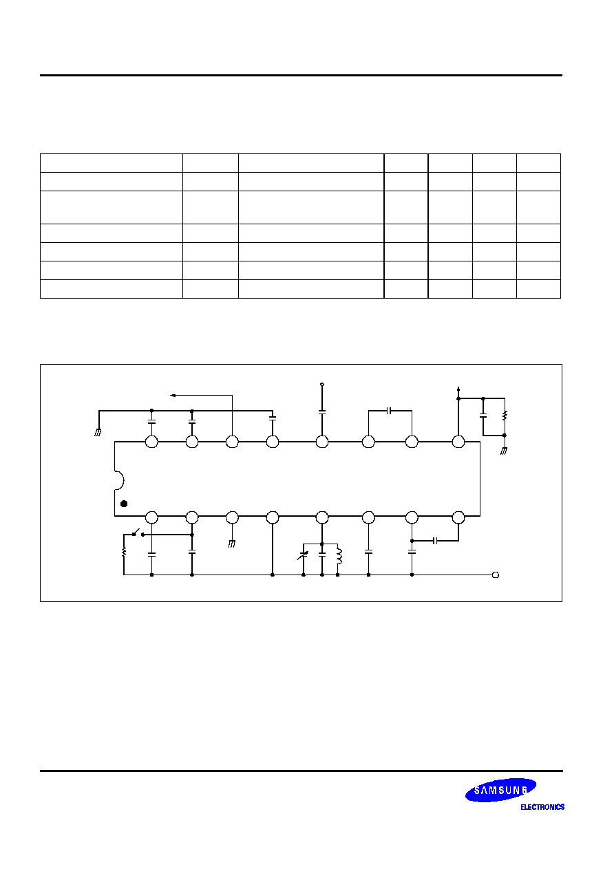
TEST CIRCUIT
Figure 2.
Characteristics
Symbol
Test conditions
Min.
Typ.
Max.
Unit
Current consumption
Icc
-
-
6.3
8.0
mA
Input for -3dB limiting
V
LIM
AFo = -3dB
0dB Ref = 150mVrms RFin
-
5.0
13
µ
Vrms
S/N ratio
S/N
-
45
60
-
dB
Detector output disctirtion
THD
DET
-
-
0.7
-
%
Recovered audio output
V
O(RA)
-
-
90
-
mVrms
AM rejection ratio
AMRR
AM modulation = 30%
40
50
-
dB
1
2
3
4
5
6
7
8
16
15
14
13
12
11
10
9
KA8532
R2
10k
C1
10n
C2
100n
GND
Cv
2-6p
C5
56p
L5
2.7
µ
F
C6
100n
C7
1.5n
C8
820p
Vcc
R9
8.2K
C9
100n
RSSI
C10
4.7n
C12
220p
RFin (98MHz)
C13
220p
C15
3.3n
C16
100n
GND
AF OUTPUT

FIL TERLESS WIDEBAND FM IF DETECTOR
KA8532
5
FINAL VERSION : 99.5.1
APPLICATION CIRCUIT ( FOR 900MHZ RF )