
AUDIO SIGNAL PROCESSOR
S1A0293A
1
INTRODUCTION
The S1A0293A is a monolithic integrated circuit for an audio
system.
The S1A0293A consists of a MIC AMP, MIC and MICOM or
Manual selection part for PHONO, TUNER, CD, TAPE, AUX,
and VTR input.
FEATURES
∑
6-Input Dual Analog Switch
∑
Dual Phono Amp
∑
Dual Buffer Amp 2
∑
Dual MIC Mix
∑
MICOM Interface for function selection.
∑
Manual function selection switch without MICOM
∑
LEC Driving circuit for indication of selected function
∑
Operating voltage : V
CC
= 6V -- 12V
ORDERING INFORMATION
Device
Package
Operating Temperature
Pitch
S1A0293A-Q1R0
48
-
QFP
-
1010E
-
20
∞
C
+ 70
∞
C
0.75 mm
48
-
QFP
-
1010E

S1A0293A
AUDIO SIGNAL PROCESSOR
2
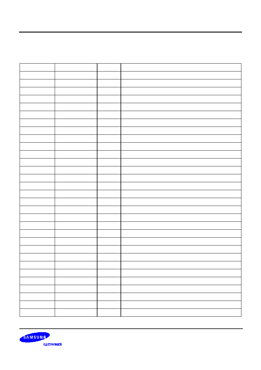
BLOCK DIAGRAM
1/2 Vcc
Analog Switch (L)
Analog Switch (R)
P H O N O A M P
A D D R E S S D E C O D E R
S - P C O N V E R T E R
S W I T C H C O N T R O L L E R
F U N C T I O N D E C O D E R
LED DRIVING CKT
1/2 Vcc
P H O N O A M P
+
_
+
_
+
_
+
_
+
_
+
_
+
_
+
_
1
2
3
4
5
6
7
8
9
1 0
1 1 1 2
1 3
1 4
1 5
1 6
1 7
1 9
2 0
2 1
2 2
2 3
1 8
2 4
2 5
2 6
2 7
2 8
2 9
3 0
3 1
3 2
3 3
3 4
3 5
3 6
3 7
3 8
3 9
4 0
4 1
4 2
4 3
4 4
4 5
4 6
4 7
4 8
M U T E
M U T E
B U F F E R 1
B U F F E R 2
B U F F E R 1
B U F F E R 2
MIC 2'n d A M P
MIC 1'st AMP
Fig. 1
AUDIO SIGNAL PROCESSOR
S1A0293A
3
PIN DESCRIPTION
Pin Description
Pin No
Symbol
I/O
Description
1
PHRIN
I
Right Channel PHONO AMP Input
2
PHRNF
I
Right Channel PHONO AMP Negative feedback
3
PHROUT
O
Right Channel PHONO AMP Output
4
RHV
CC
-
Right Channel 1/2 V
CC
5
BFR1 OUT
O
Right Channel 1st Buffer Output
6
BFR2 INPUT
I
Right Channel 2nd Buffer Input
7
BRF2 NF
I
Right Channel 2nd Buffer Negative feedback
8
BFR2 OUT
O
Right Channel 2nd Buffer Output
9
MIC 2/N
I
Mic 2nd AMP Input
10
MIC 1OUT
O
Mic 1st AMP Output
11
MIC1
I
Mic 1st AMP Negative feedback
12
MIC
I
Mic 1st AMP Input
13
MSPH
I/O
Manual Selection S/W for PHONO function
14
MSTU
I/O
Manual Selection S/W for Tuner function
15
MSCD
I/O
Manual Selection S/W for Compact Disc
16
MSTA
I/O
Manual Selection S/W for Tape
17
MSAU
I/O
Manual Selection S/W for Aux
18
MSVT
I/O
Manual Selection S/W for VTR
19
D-GND
-
Digital GND
20
RESET
-
RESET
21
MUTIN
I
Not use
22
CEIN
I
Enable Input from MICOM
23
CLIN
I
Clock Input from MICOM
24
DAIN
I
DATA Input from MICOM
25
u/M SEL
-
u-com/Manual Selection
26
MUTIM
-
Muting time decision during Manual Control
27
V
CC
-
V
CC
(Digital)
28
V
CC
-
V
CC
(Analog)
29
BFL2 OUT
O
Left Channel 2nd Buffer Output pin
30
BFL2 NF
I
Left Channel 2nd Buffer Negative feedback
31
BFL2 INT
I
Left Channel 2nd Buffer Input

S1A0293A
AUDIO SIGNAL PROCESSOR
4
32
MFL1 OUT
O
Left Channel 1st Buffer Output
33
RRF/L
-
Ripple Rejection filter
34
LHV
CC
-
Left Channel 1/2 V
CC
35
PHLOUT
O
Left Channel PHONO Ouptut
36
PHLNF
I
Left Channel PHONO AMP Negative feedback
37
PHLIN
I
Left Channel PHONO AMP Input
38
TULIN
I
Left Channel Tuner Input
39
CDLIN
I
Left Channel Compact Disc Input
40
TALIN
I
Left Channel TAPE Input
41
AULIN
I
Left Channel Aux Input
42
VTLIN
I
Left Channel VTR Input
43
A-GND
-
Analog GND
44
VTR IN
I
Right Channel VTR Input
45
AUR IN
I
Right Channel Aux Input
46
TAR IN
-
Right Channel TAPE Input
47
CDRIN
I
Right Channel Compact Disc Input
48
TURIN
I
Right Channel Tuner Input
Pin Description (Continued)
Pin No
Symbol
I/O
Description

AUDIO SIGNAL PROCESSOR
S1A0293A
5
ABSOLUTE MAXIMUM RATINGS (Ta = 25
∞
C)
ELECTRICAL CHARACTERISTICS
(V
CC
= 12V, f = 1kHz unless otherwise specified).
Characteristic
Symbol
Value
Unit
Supply Voltage
V
CC
12
V
Power Dissipation
P
D
400
mW
Operating Temperature
T
OPR
-
20
-
75
∞
C
Storage Temperature
T
STG
-
55
-
125
∞
C
Characteristic
Symbol
Test Conditions
SPEC
UNIT
Min.
Typ.
Max.
Quiescent Circuit
Manual
I
CCQ
1
LED Currnet
25
40
55
mA
Current
u-Com
I
CCQ
2
Exception
20
35
50
Function Begining Selection
Vfo
Manual Mode
-
0.2
0.5
V
Function Indication Selection
Vf1
Manual / u-Com
-
0.2
0.5
V
Phono Amp Close Loop Gain
G
VP
f = 1kHz
34
35
36
dB
1st Amp Close Loop Gain
G
VB
1
f = 1kHz
5
6
7
dB
2nd Amp Close Loop Gain
G
VB
2
f = 1kHz
5
6
7
dB
1st Mic Amp Gain
Gvm1
f = 1kHz
33
34
35
dB
2st Mic Amp Gain
Gvm2
f = 1kHz
5
6
7
dB
Analog S/W Max Input Voltage
Vin amx
f = 1kHz, THD = 1%
1.2
1.5
-
Vrms
1st Buffer Max Ouptut Voltage
Vob 1max f = 1kHz, THD = 1%
2.5
3.0
-
Vrms
2st Buffer Max Ouptut Voltage
Vobmax
f = 1kHz, THD = 1%
2.5
3.0
-
Vrms
1st Mic Max Output Voltage
Vom1max f = 1kHz, THD = 1%
1.2
1.5
-
Vrms
Function Cross Talk
CT1
f = 1kHz R
G
= 4.7k
V
OB2
= 1V
RMS
75
85
-
dB
Channel Cross
Talk
Phono
CT2
f = 1kHz R
G
= 0
55
65
-
dB
Phono exception
CT3
V
OB2
= 1V
RMS
65
75
-
S/N ratio
Phono
S/N 1
f = 1kHz R
G
= 0
55
65
-
dB
Phono exception
S/N2
V
OB2
= 200mV
RMS
75
85
-
THD
Phono
THD1
f = 1kHz R
G
= 0
-
0.05
0.1
%
Phono exception
THD2
V
OB2
= 1V
RMS
-
0.03
0.05

S1A0293A
AUDIO SIGNAL PROCESSOR
6
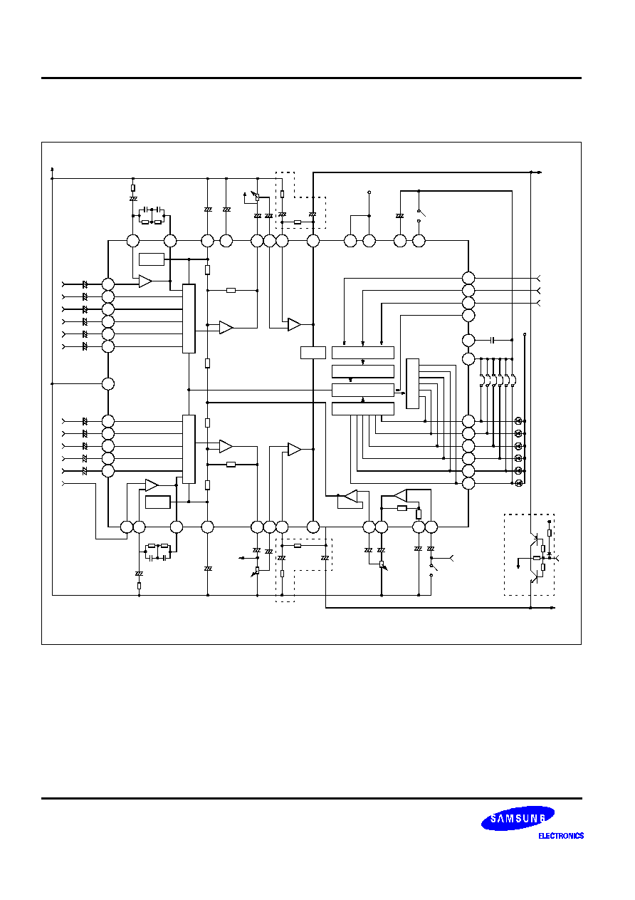
TEST CIRCUIT
1/2 Vcc
Analog Switch (L)
Analog Switch (R)
PHONO AMP
ADDRESS DECODER
S-P CONVERTER
SWITCH CONTROLLER
LED DRIVING CKT
1/2 Vcc
PHONO AMP
+
_
+
_
+
_
+
_
+
_
+
_
+
_
+
_
19
20
21
25
26
27
28
33
MUTE
MUTE
BUFFER 1
BUFFER 2
BUFFER 1
BUFFER 2
MIC 2`nd AMP
MIC 1`nt AMP
FUNCTION DECODER
13
14
15
16
17
18
22
23
24
<
<
<
+
29
30
31
32
34
36
35
11 12
9
10
+
+
+
+
E
4
5
6
7
8
B
+
+
+
+
A
+
2
D
+
+
+
+
C
+
+
37
38
39
40
41
42
43
44
45
46
47
48
1
+
+
+
+
+
+
+
+
+
+
+
+
3
PHONO
TUNER
TAPE
AUX
VTR
CD
TUNER
TAPE
AUX
VTR
CD
DATA
CLOCK
ENABLE
100
220
0.56u 0.016u
56K
4.7K
220u
100u
4.7K
10K
4.7u
47u
47u
10K
4.7u
4.7u
VCC 1.2V
S1
10u
0.01u
VDD-5V
470
470
470
470
470
470
V
C1
V
C2
V
C3
V
C4
V
C5
V
C6
VSM
S5
56K 4.7K
0.056u 0.016u
220u
100
+
220u
47u
47u
47u
47u
10K
10K 10K
47u
47u
47u
47u
47u
47u
S4
4.7K
4.7K
47
µ
PHONO
4.7K

AUDIO SIGNAL PROCESSOR
S1A0293A
7
APPLICATION INFORMATION
Logic Part
First of all, if you let the MICOM operate, pin 25 has to connect to the GND.
The S1A0293A obtains the MICOM data such as the following: timing diagram, and then, converts the data from
serial to parallel type by the use of internal analog switches.
The signal input from MICOM, consists of the 12-bit serial data, and the data consists of the 4-bit address and the
8-bit data for the selection of the switch input.
DATA INPUT METHOD
ADDRESS
DATA
PHONO
0101
10000000
TUNER
0101
01000000
CD
0101
00100000
TAPE
0101
00010000
AUX
0101
00001000
VTR
0101
00000100
A
0
CLOCK
DATA
CE
A
1
A
2
A
3
A
4
Sig
S1A0293A
AUDIO SIGNAL PROCESSOR
8
APPLICATION CIRCUIT
37
38
39
40
41
42
43
44
45
46
47
48
1
2
3
4
5
6
7
8
9 10
11 12
13
14
15
16
17
18
19
20
21
22
23
24
25
26
27
28
29
30
31
32
33
34
35
36
+
-
1/2 V
CC
A
n
a
l
o
g
S
w
i
t
c
h
(
L
)
+
-
+
-
+
-
+
-
A
n
a
l
o
g
S
w
i
t
c
h
(
R
)
+
-
MUTE
ADDRESS DECODER
S-P CONVERTER
SWITCH CONTROLLER
FUNCTION DECODER
L
E
D
D
R
I
V
I
N
G
C
K
T
+
-
+
-
1/2 V
CC
+
+
+
+
+
+
+
+
+
+
+
+
+
+
+
+
+
+
+
+
+
+
+
+
+
+
+
4.7
µ
4.7
µ
4.7
µ
4.7
µ
4.7
µ
4.7
µ
PHONO
TUNER
CD
TAPE
AUX
VTR
VTR
AUX
TAPE
CD
TUNER
PHONO
56K 4.7K
0.056
µ
0.016
µ
220
µ
100
220
µ
220
µ
+
2
2
0
µ
REC
10K
10K
47
µ
10K
47
µ
47
µ
47
µ
10K
47
µ
47
µ
S2
5.6K
5
.
6
K
22K
M
U
T
E
PWR
AMP
0.01
µ
VDD-
5V
CE
CLOCK
DATA
PWR
AMP
S1
10
µ
47
µ
10K
47
µ
1
0
K
REC
10K
47
µ
+
47
µ
220
µ
100
µ
100
220
µ
0.056
µ
0.016
µ
56K 4.7K