
5 DOT LED LEVEL METER DRIVER
S1A2284A04
1
INTRODUCTION
The S1A2284A04 is a monolithic integrated circuit designed for
5-dot LED level meter drivers with a built-in rectifying amplifier.
It is suitable for AC/DC level meters such as VU meters or sig-
nal meters.
FEATURES
∑
High gain rectifying amplifier included (Gv = 26dB)
∑
Low radiation noise when LED turns on
∑
Linear indicator for 5-dot bar type LED
(0.33, 0.67, 1, 1.33, 1.67)
∑
Constant current output
S1A2284A04: I
O
= 15mA (Typ)
∑
Wide operating supply voltage range:
V
CC
= 3.5V
-
16 V
∑
Minimum number of external parts required
ORDERING INFORMATION
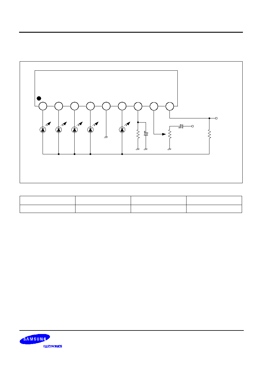
BLOCK DIAGRAM
Device
Package
Operating Temperature
ID
S1A2284A04-I0U0
9
-
SIP
-
20
∞
C
-
+ 80
∞
C
15mA
9
-
SIP
1
2
3
4
5
6
7
8
9
D5
D4
D3
D2
D1
LED DRIVER
REFERENCE VOLTAGE
D1
D2
D3
D4
GND
D5
OUTPUT
INPUT
V
CC

S1A2284A04
5 DOT LED LEVEL METER DRIVER
2
ABSOLUTE MAXIMUM RATINGS (Ta = 25
∞
C)
NOTE:
11mW/
∞
C = C is decreased at higher temperatures than Ta = 25
∞
C.
ELECTRICAL CHARACTERISTICS
(Ta =25
∞
C, V
CC
= 6V, f =1kHz, unless otherwise specified)
NOTE: Definition of 1; Pin 3 voltage when V
CL (ON)3
turn on (65mV)
Characteristic
Symbol
Value
Unit
Supply Voltage
V
CC
18
V
Amp Input Voltage
V
8-5
-0.5
-
V
CC
V
Pin 7 Voltage
V
7-5
6
V
D Terminal Output Voltage
V
D
18
V
Circuit Current
I
CC
12
mA
D Terminal Output Current
I
D
20
mA
Power Dissipation
P
D
1100
mW
Operating Temperature
T
OPR
-
20
-
+80
∞
C
Storage Temperature
T
STG
-
40
-
+125
∞
C
Characteristic
Symbol
Test Conditions
Min.
Typ.
Max.
Unit
Quiescent Circuit Current
I
CCQ
V
I
= 0V
-
6
8.5
mA
D Output Current
I
O
V
I
= 0.15V
11
15
18.5
mA
Input Bias Current
I
BIAS
-
-
1
-
0
µ
A
Amp Gain
G
V
V
I
= 0.1V
24
26
28
dB
V
CL(ON)1
0.28
0.33
0.40
V
CL(ON)2
0.59
0.67
0.75
Comparator On Level
V
CL (ON)
V
CL(ON)3
-
-
1
-
V
3
V
CL(ON)4
1.25
1.33
1.42
V
CL(ON)5
1.48
1.67
1.87
5 DOT LED LEVEL METER DRIVER
S1A2284A04
3
TEST CIRCUIT
The recommended value of R at T
a
(max) = 60
∞
C.
By changing the time constant C
1
and the response C
2
, attack and release time may be varied. In the above appli-
cation conditions, power dissipation may be operated at higher levels than the absolute maximum ratings.
The wattage of R is to be determined by the total LED current and R value recommended by the R table.
V
CC
(V)
8
-
12
10
-
14
12
-
16
R(
)
47
68
91
D1
10µ
F/16V
10k
D2
D3
D4
D5
10k
2.2µ
F/16V
INPUT
C1
R
Vcc
C2
C2 : AC in, 2.2
µ
F is used.
DC in, 2.2
µ
F is shorted.
S1A2284A04
1
2
3
4
5
6
9
8
7

S1A2284A04
5 DOT LED LEVEL METER DRIVER
4
NOTES