COMPANDER WITH ALC
S1T8512B
1
INTRODUCTION
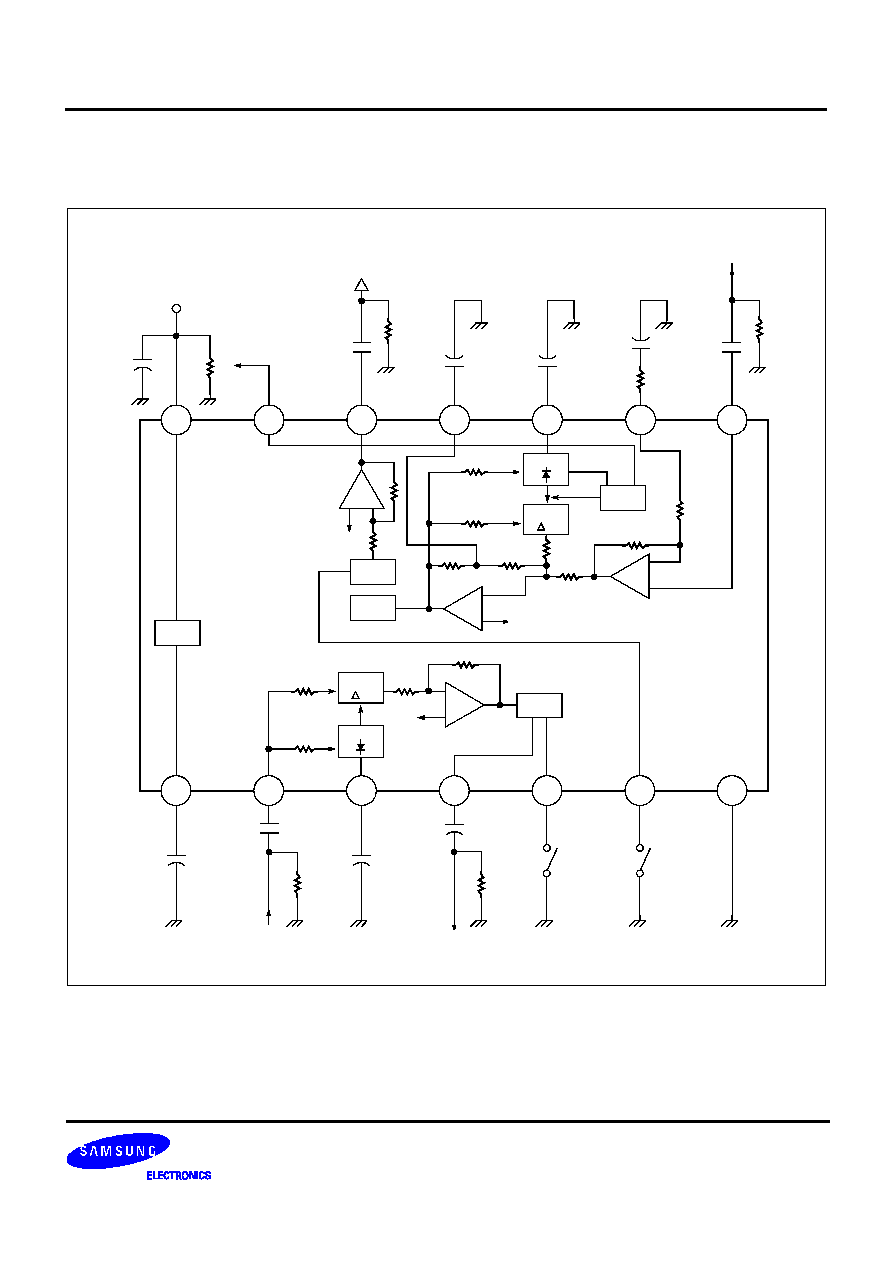
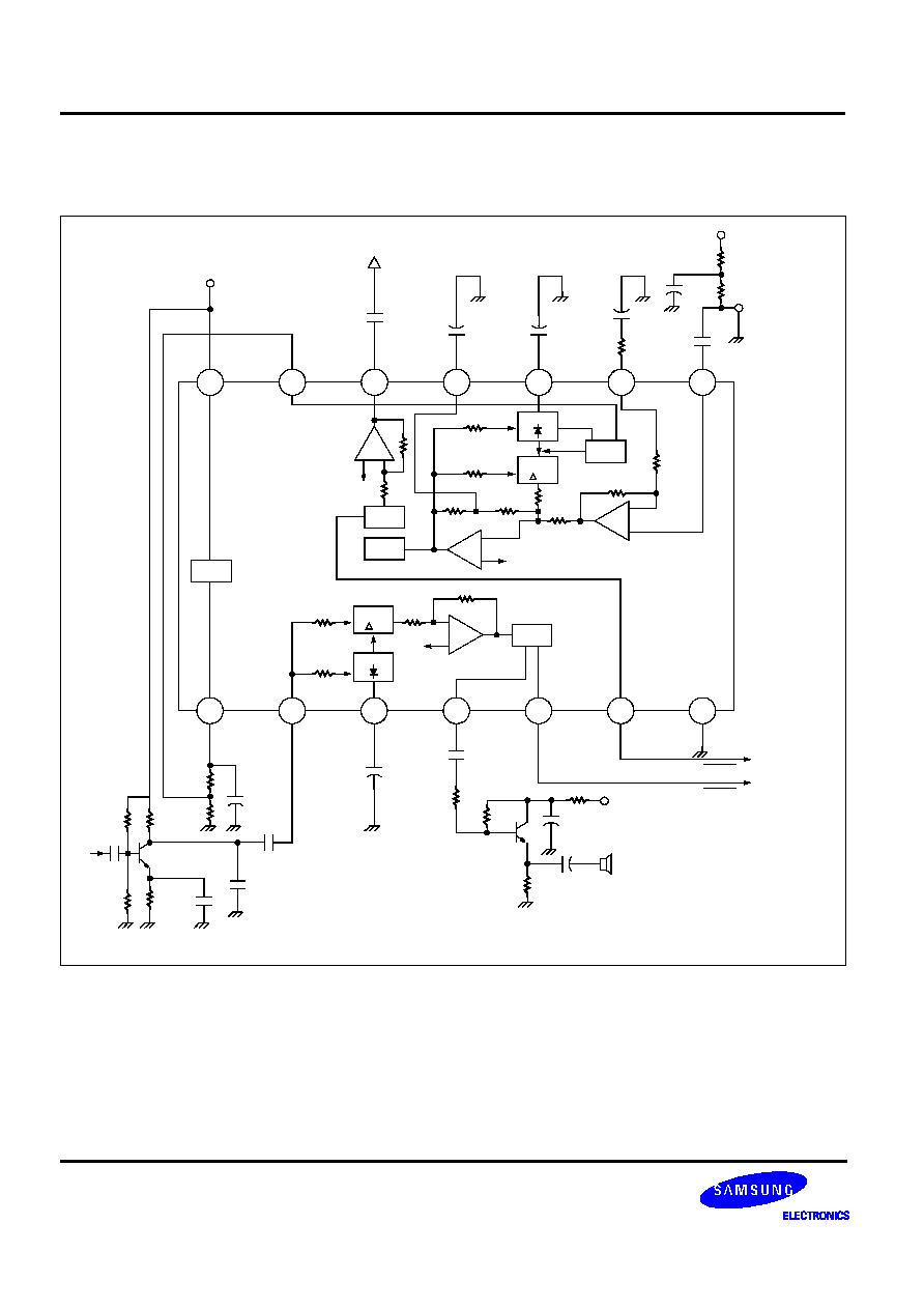
Compander is a composite word of compressor and expander. It is
used for maintaining dynamic range and improving of S/N ratio, and is
generally called as a noise reduction system or automatic gain control
system.
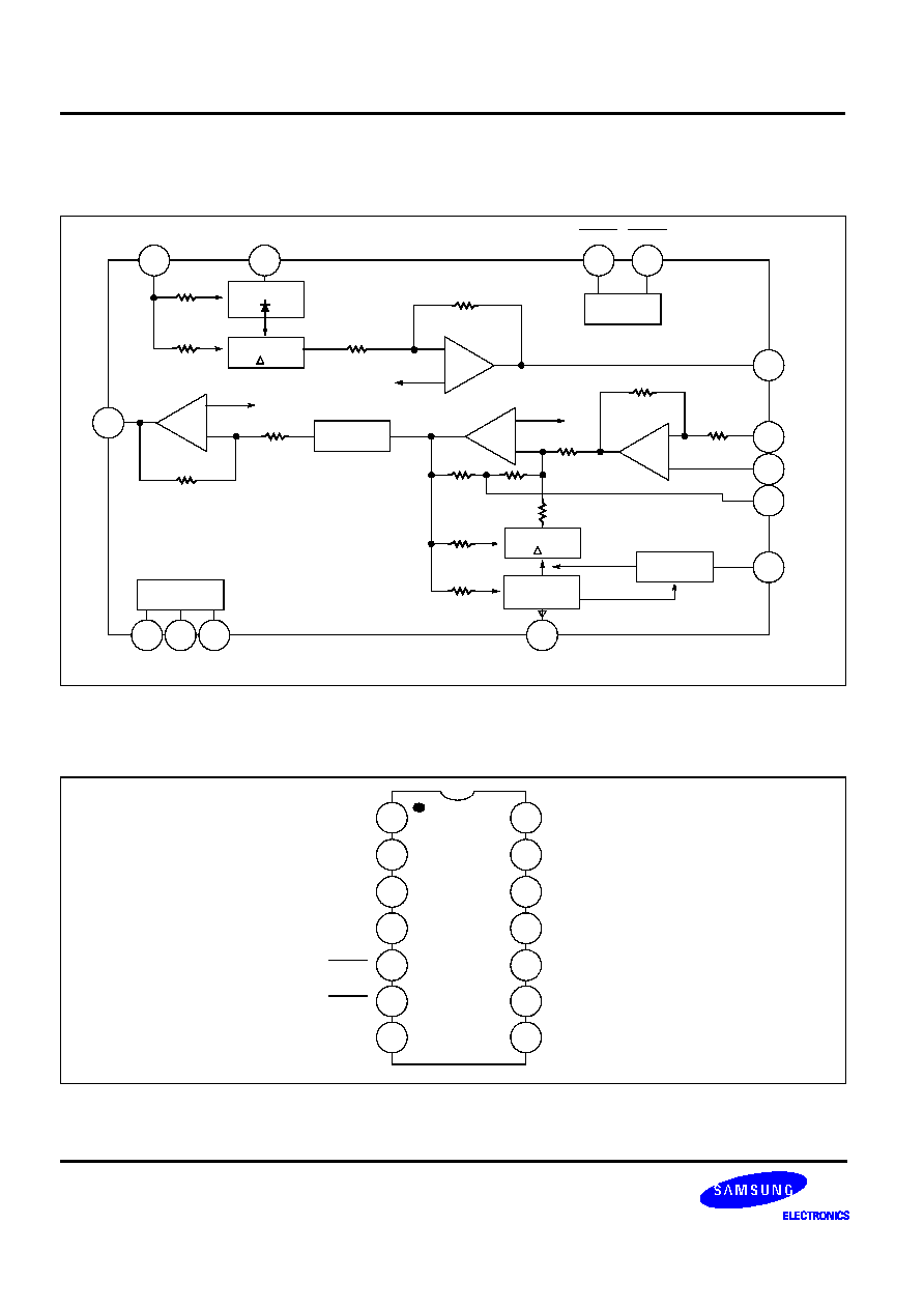
S1T8512B consists of compressor, expander, mic amp, Iimiter, ALC
(automatic level control) and mute logic.
FEATURES
∑
Operating voltage range: 2 to 6V
∑
Included ALC circuit
∑
Easy gain control to use external component
∑
Included mute function
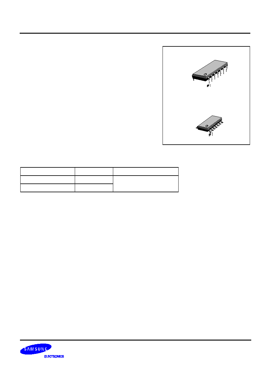
ORDERING INFORMATION
Device
Package
Operating Temperature
S1T8512B01-D0B0
14
-
DIP
-
300
-
20
∞
C to +70
∞
C
S1T8512B01-S0B0
14
-
SOP
-
225B
14
-
DIP
-
300
14
-
SOP
-
225B
COMPANDER WITH ALC
S1T8512B
3
PIN DESCRIPTION
Pin No
Symbol
Description
1
V
REF
It is a voltage reference (V
REF
= 1V) used for supplying a constant voltage to the
compressor and expander of compander.
2
EPI
It is SUM AMP input terminal of expander. The voice signal recovered after the
demodulation waveform from the receiver passed through the 2nd order low pass filter
enters this terminal.
3
ERC
This terminal is used for converting waveform from the full wave rectifier to DC element at
the rectifier block of expander (R X C = 22msec)
4
EO
It is an output terminal of expander, which comes out the regenerated voice signal .
5
EMUTE
It is an expander mute terminal of compander and the final mute block of an expander
located next to the receiver terminal. It blocks the data signal of MCU being transmitted to
an user, and is connected to the RX mute terminal of MCU. Expanding is executed if this
terminal set to high, and expander mute is executed if it set to low.
6
CMUTE
It is compressor mute terminal of a compander. Mute block is used to avoid duplication of
data transmission from MICOM (Between the base and hand set) with the voice signal. It
is connected to the TX mute terminal of MICOM. Compressing is executed if the terminal
set to high, and compressor mute is executed if it set to low.
7
GND
It is ground terminal.
8
CPI+
It is a MIC AMP non-inverting input terminal of compressor, and is used as an input
terminal for voice signal.
9
CPI
-
It is a MIC AMP inverting input terminal of compressor, and is used for adjusting the
negative feedback loop gain. (In application, gain is about 5)
10
CRC
This terminal is used for converting waveform from the full wave rectifier to DC element at
the rectifier block of compressor. (R X C = 22msec)
11
AGIC
This terminal is used for bypassing an AC element at the feed-back loop which comes
from the SUM AMP block of compressor. A capacitor should be connected between this
terminal and GND.
12
CO
It is a compressor output terminal of compander, and is connected to the modulation input
terminal of transmitter.
13
ALC
It is a reference voltage input terminal of ALC (Automatic Level Control). ALC circuit may
be turned off according to the ALC reference voltage, magnitude of output voltage may
be limited if it is used for adjusting THD of output voltage of compressor to less than 3%
or to limit the frequency of TX in case the input is higher than a certain level.
14
V
CC
It is supply voltage terminal.