 | –≠–ª–µ–∫—Ç—Ä–æ–Ω–Ω—ã–π –∫–æ–º–ø–æ–Ω–µ–Ω—Ç: S3C2800X | –°–∫–∞—á–∞—Ç—å:  PDF PDF  ZIP ZIP |

S3C2800
32-BIT RISC MICROPROCESSOR
DATA SHEET
Revision 1.0

Important Notice
The information in this publication has been carefully
checked and is believed to be entirely accurate at the
time of publication. Samsung assumes no
responsibility, however, for possible errors or
omissions, or for any consequences resulting from the
use of the information contained herein.
Samsung reserves the right to make changes in its
products or product specifications with the intent to
improve function or design at any time and without
notice and is not required to update this documentation
to reflect such changes.
This publication does not convey to a purchaser of
semiconductor devices described herein any license
under the patent rights of Samsung or others.
Samsung makes no warranty, representation, or
guarantee regarding the suitability of its products for
any particular purpose, nor does Samsung assume
any liability arising out of the application or use of any
product or circuit and specifically disclaims any and all
liability, including without limitation any consequential
or incidental damages.
"Typical" parameters can and do vary in different
applications. All operating parameters, including
"Typicals" must be validated for each customer
application by the customer's technical experts.
Samsung products are not designed, intended, or
authorized for use as components in systems
intended for surgical implant into the body, for
other applications intended to support or sustain
life, or for any other application in which the failure
of the Samsung product could create a situation
where personal injury or death may occur.
Should the Buyer purchase or use a Samsung
product for any such unintended or unauthorized
application, the Buyer shall indemnify and hold
Samsung and its officers, employees, subsidiaries,
affiliates, and distributors harmless against all
claims, costs, damages, expenses, and
reasonable attorney fees arising out of, either
directly or indirectly, any claim of personal injury or
death that may be associated with such
unintended or unauthorized use, even if such
claim alleges that Samsung was negligent
regarding the design or manufacture of said
product.
S3C2800 32-Bit Microprocessor
Data Sheet, Revision 1.0
Publication Number:
11.0-S3-C2800-072002
© 2002 Samsung Electronics
All rights reserved. No part of this publication may be reproduced, stored in a retrieval system, or transmitted in
any form or by any means, electric or mechanical, by photocopying, recording, or otherwise, without the prior
written consent of Samsung Electronics.
Samsung Electronics' microcontroller business has been awarded full ISO-14001
certification (BSI Certificate No. FM24653). All semiconductor products are designed
and manufactured in accordance with the highest quality standards and objectives.
Samsung Electronics Co., Ltd.
San #24 Nongseo-Lee, Giheung-Eup
Yongin-City, Gyeonggi-Do, Korea
C.P.O. Box #37, Suwon 449-900
TEL: (82)-(31)-209-6530
FAX: (82)-(31)-209-6547
Home-Page URL: Http://www.samsungsemi.com
Printed in the Republic of Korea

S3C2800
32-Bit RISC
Microprocessor
Data Sheet
OVERVIEW
SAMSUNG's S3C2800 32-bit RISC microprocessor is designed to provide a cost-effective and high-performance
micro-controller solution for general applications. The S3C2800 features the following integrated on-chip support
to help design a system a low cost: 16KB I/D caches, 2-ch UART with handshake, 4-ch DMA, memory controller,
3-ch timer, GPIO (General-Purpose Input/Output) ports, RTC (Real Time Clock), 2-ch IIC-BUS interface, and a
built-in PLL for system clock.
Based on ARM920T core, the S3C2800 is developed using 0.18 um CMOS standard cells and a memory
compiler. Its simple, elegant, and fully static low-power design is particularly suitable for both cost-sensitive and
power-sensitive applications. The 32-bit ARM920T RISC processor core (220Mips @200MHz), designed by
Advanced RISC Machines, Ltd., provides architectural enhancements such as the Thumb de-compressor, a 32-
bit hardware multiplier, and an on-chip ICE debug support. Also, the S3C2800 features the Harvard BUS
architecture for efficient data/instruction transfers.
By integrating various common system peripherals, the S3C2800 minimizes the overall system cost and
eliminates the need to configure additional components. The integrated on-chip functions are summarized as
follows :
∑
PCI BUS interface (32-bit, up to 66MHz).
∑
1.8V static ARM920T CPU core with 16KB I/D (Instruction/Data) cache. (Harvard bus architecture up to
200MHz).
∑
External memory controller. (FP/EDO/SDRAM control, Chip select logic).
∑
4-ch general DMAs with external request pins.
∑
2-ch UART with handshake (IRDA1.0, 16-byte FIFO), Modem Interface.
∑
2-ch multi-master IIC-BUS controller.
∑
3-ch 16-bit timer.
∑
16-bit Watchdog timer.
∑
44 general-purpose GPIO ports including 8 external interrupt source.
∑
Power management: Normal, Slow, and Idle modes.
∑
RTC with calendar function.
∑
On-chip PLL clock generator.

S3C2800 MICROCONTROLLER DATA SHEET
2
FEATURES
Architecture
∑ Little-/Big-endian support for external memory.
∑
Address space: 32Mbytes per each bank (Total
256Mbyte)
∑
Supports programmable 8/16/32-bit data bus
width for each memory bank
∑
Fixed bank start address for all (static memory
and dynamic memory banks)
∑
8 memory banks
≠ 4 memory banks for static memory (ROM,
SRAM, FLASH etc)
≠ 4 memory banks for dynamic memory (Fast
Page, EDO, and Synchronous DRAM)
∑
Fully programmable access cycles for all static
memory banks
∑
Supports external wait signal to extend the bus
cycle
∑
Supports self-refresh mode in DRAM/SDRAM.
∑
Supports asymmetric/symmetric address of
DRAM
I/D (Instruction/Data) Cache Memory
∑
64-way set-associative ICache (16KB) and
DCache (16KB)
∑
8 words per line with one valid bit and 2 dirty
bits per line
∑
Pseudo-random or round-robin replacement
algorithm
∑
Write-through and Write-back cache operation.
∑
The write buffer can hold 16 words of data and 4
addresses
∑
Low voltage cache for reduced power
consumption
Clock & Power Manager
∑
The on-chip PLL generates the necessary clock
for the operation of MCU at maximum of
200MHz@1.8V
∑
Input frequency range: (Fin) = 6MHz ≠ 10MHz.
∑
Output frequency range: (F
CLK
) = 20MHz ≠
200MHz
∑
Clock can be selectively provided to each
function block by software
∑
Power Down Mode: NORMAL, SLOW, and IDLE
mode
≠ NORMAL mode: Normal operating mode
≠ SLOW mode: Low frequency clock without
PLL
≠ IDLE mode: Clock to CPU is disabled
PCI Bus Interface
∑
Embedded PCI Host Bridge
∑
32-bit data bus at 66MHz

DATA SHEET S3C2800 MICROCONTROLLER
3
FEATURES (Continued)
Interrupt Controller
∑
34 Interrupt sources.
(3 for Timers, 6 for UART, 8 for External
interrupts, 4 for DMA, 2 for RTC, 2 for IIC, 2 for
RCSR (Remote Control Signal Receiver), and 7
for
PCI))
∑
Software polling Interrupt mode
∑
Selectable level- or edge-triggered external
interrupts source
∑
Programmable IRQ/FIQ for each interrupt
request
∑
Supports FIQ (Fast Interrupt Request) for very
urgent interrupt request
Timer
∑
3-ch 16-bit Timer with DMA-based or interrupt-
based operation
Watchdog Timer
∑
16-bit Watchdog Timer
RCSR (Remote Control Signal Receiver)
∑
8-step FIFO
∑
FIFO interrupt is generated on full (8) step
overflow
RTC (Real Time Clock)
∑
Full clock feature: sec, min, hour, date, day,
week, month, and year
∑
32.768 kHz input clock
∑
Alarm interrupt
∑
Time tick interrupt
GPIO (General-Purpose Input/Output) Ports
∑
8 external interrupt ports
∑
44 multiplexed input/output ports.
UART
∑
2-channel UART with DMA-based or interrupt
based operation
∑
Supports 5-bit, 6-bit, 7-bit, or 8-bit serial data
transmit/receive
∑
Supports hardware handshaking during
transmit/receive operation
∑
Programmable baud rates (up to 230.4Kbps).
∑
Supports IrDA 1.0 (up to 115.2Kbps)
∑
Loop back mode for testing
∑
Program accessible 16-byte FIFO (2x16 byte
FIFO for transmit/receive data)
DMA Controller
∑
4-channel general-purpose Direct Memory
Access controller without CPU intervention.
∑
Support memory to memory, memory to I/O and
I/O to I/O DMA operations of the following 6
types:
Software, 3 internal function blocks (UART0,
UART1, Timer), and 2 External requests
∑
Burst transfer mode to enhance the transfer rate
on the FPDRAM, EDODRAM and SDRAM
IIC-BUS Interface
∑
2-ch Multi-Master IIC-Bus with interrupt-based
operation
∑
Serial, 8-bit oriented, bi-directional data
transfers at up to 100 Kbit/s in the standard
mode or up to 400 Kbit/s in the fast mode
Operating Voltage Range
∑
Core: 1.8 V -0.1 V/+0.15 V
∑
I/O: 3.3 V
±
0.3 V
Operating Frequency
∑
Up to 200 MHz.
Package
∑
208-pin LQFP

S3C2800 MICROCONTROLLER DATA SHEET
4
BLOCK DIAGRAM
AHB to APB Bridge
2ch-IIC
2ch-IIC
2ch-IIC
2ch-IIC
Watch-dog
RTC
2ch-IIC
RMT Receive
Memory
Controller
PCI Bridge
4ch-GDMA
Arbiter/Decode
AMBA bus
Interface
ASB
ASB to AHB bus Bridge
AHB BUS 32-bit
BUS Controller
Arbiter/Decode
Interrupt
Controller
Clock(PLL) &
Power Manage
2ch-IIC
GPIO
2ch-UART
3ch-Timers
AHB to APB Bridge
APB BUS 32-bit
Write
buffer
Write back
PA tag
RAM
Data cache
Data MMU
ARM9TDMI
Processor core
(Integral
EmbeddedICE)
External
coproc
interface
Instruction
cache
Instruction
MMU
CP15
WBPA[31:0]
DPA[31:0]
DVA[31:0]
DD[31:0]
ID[31:0]
IPA[31:0]
IVA[31:0]
IV
2
A[31:0]
DV
2
A[31:0]
JTAG
C13
C13
Figure 1. S3C2800 Block Diagram

PRELIMINARY DATA SHEET S3C2800 MICROCONTROLLER
5
PIN DIAGRAM (208-LQFP)
S3C2800X
208-LQFP
VSS3OP
VDD3OP
PCI_AD27
PCI_AD26
PCI_AD25
PCI_AD24
120
119
118
117
129
130
131
132
133
134
135
136
137
138
139
140
141
142
143
144
145
146
147
148
149
150
151
152
153
154
155
156
PCI_AD17
PCI_AD16
VSS3OP
PCI_C2/nBE2
PCI_nFRAME
PCI_nIRDY
VDD3OP
PCI_nTRDY
PCI_PAR
PCI_nSERR
PCI_nPERR
PCI_nLOCK
PCI_nSTOP
PCI_nDEVSEL
PCI_C1/nBE1
PCI_AD15
VSS3OP
PCI_AD14
PCI_AD13
PCI_AD12
PCI_AD11
PCI_AD6
PCI_AD9
PCI_C0/nBE0
VDD3OP
PCI_AD8
PCI_AD7
PCI_AD10
PCI_AD19
121
122
123
124
125
126
127
128
PCI_C3/nBE3
PCI_IDSEL
PCI_AD23
PCI_AD22
VDD
VSS
PCI_AD21
PCI_AD20
PCI_AD18
105
106
107
108
109
110
111
112
113
114
115
116
53
54
55
56
57
58
60
59
65
64
63
62
61
68
67
66
74
73
72
71
70
69
76
77
78
79
80
75
86
85
84
83
82
81
88
89
90
91
92
87
nOE
nWE
41
42
43
44
45
46
47
48
49
50
51
52
VDD3OP
VSS3OP
DATA29
DATA30
DATA31
GPB6/nWAIT
GPB7/CLKout
GPC0
GPC1
GPC2
GPC3/ENDIAN
nTRST
TCK
TMS
TDI
TDO
IRIN
GPD0/IICSDA0
GPD1/IICSCLK0
GPD2/IICSDA1
GPD6/nCTS0
GPD5/TxD0
GPD4/RxD0
GPD3/IICSCLK1
GPD7/nRTS0
nRESET_OUT
GPE0/RxD1
GPE1/TxD1
GPE2/nCTS1
GPE3/nRTS1
VDD
VSS
GPE4/nXDREQ0
GPE5/nXDACK0
GPE6/nXDREQ1
GPE7/nXDACK1
GPF0/EXTINT0
GPF1/EXTINT1
1
nSDCS2/nDRAS2/GPA4
nSDCS3/nDRAS3/GPA5
VDD3OP
VSS3OP
nDCAS0/GPA6
nDCAS1/GPA7
nDCAS2/nSDCAS/GPB0
nDCAS3/nSDRAS/GPB1
SDCKE
SDCLK
ADDR17
DATA17
nBE0/nWBE0/DQM0/GPB2
nBE1/nWBE1/DQM1/GPB3
nBE2/nWBE2/DQM2/GPB4
nBE3/nWBE3/DQM3/GPB5
DATA16
ADDR16
DATA18
181
182
183
184
185
186
187
188
189
190
191
192
193
194
195
196
197
198
199
200
201
202
203
204
205
206
207
208
2
3
4
5
6
7
8
9
10
11
12
13
14
15
16
17
18
19
20
21
22
23
24
25
26
27
28
ADDR18
VDD3OP
VSS3OP
DATA19
ADDR19
DATA20
ADDR20
VDD
VSS
ADDR5
DATA7
ADDR7
DATA8
ADDR8
DATA9
ADDR9
VDD
VSS
DATA10
ADDR10
DATA11
ADDR11
VSS3OP
nSDCS1/nDRAS1/GPA3
DATA15
nSCS3/GPA2
nSCS2/GPA1
nSDCS0/nDRAS0
nSCS0
ADDR13
ADDR12
ADDR14
VDD3OP
DATA12
DATA13
DATA14
ADDR15
nSCS1/GPA0
ADDR23
DATA24
29
30
31
32
33
34
35
36
37
38
39
40
DATA21
ADDR21
DATA22
ADDR22
DATA23
ADDR24
DATA25
DATA26
DATA27
DATA28
169
170
171
172
173
174
175
176
177
178
179
180
DATA2
ADDR2
DATA3
ADDR3
VDD3OP
VSS3OP
DATA4
ADDR4
DATA5
DATA6
ADDR6
GPF2/EXTINT2
GPF3/EXTINT3
GPF4/EXTINT4
GPF5/EXTINT5
GPF6/EXTINT6
GPF7/EXTINT7
VDD3OP
VSS3OP
XTAL0
EXTAL0
TEST
nRESET
157
158
159
160
161
162
163
164
165
166
167
168
PCI_AD5
VSS3OP
PCI_AD4
PCI_AD3
PCI_AD2
PCI_AD1
PCI_AD0
PCI_nINTA
DATA0
DATA1
ADDR1
PCI_nREQ1
VSS3OP
PCI_nREQx2
PCI_nREQx3
PCI_AD31
XTAL1
EXTAL1
OM0
OM1
AVDD
PLLCAP
AVSS
PCI_nRST
PCI_CLK
PCI_nGNT1
PCI_nGNTx2
PCI_nGNTx3
98
97
96
95
94
93
100
101
102
103
104
99
ADDR0
PCI_AD29
PCI_AD28
PCI_AD30
VDD/VSS
: Internal 1.8V power
AVDD/AVSS
: Analog 1.8V Power
VDD3OP/VSS3OP : I/O 3.3V power
Figure 2. S3C2800 Pin Assignment (208-LQFP)

S3C2800 MICROCONTROLLER DATA SHEET
6
PIN ASSIGNMENTS
Table 1. Pin Assignment Description
I/O Type
Descriptions
vdd1ih, vss3I
vdd1ih_pci, vss3I_pci
1.8V power/ground for internal logic
vdd1t_abb, vss1t_abb
1.8V power/ground for analog circuitry
vdd3op, vss3op
vdd3op_pci, vss3op_pci
3.3V power/ground for external interface logic
poar50_abb
1.8V analog output (A capacitor is connected between the pin and analog ground)
phsoscm16
Oscillator cell width enable and feedback resistor (6 M ≠ 40 MHz)
phsosck17
Oscillator cell width enable and feedback resistor (≠ 100 kHz)
Phis
3.3V interface LVCMOS schmitt trigger level input buffers
Phisu
3.3V interface LVCMOS schmitt trigger level input buffers with 100 K
pull-up
resistor.
phob8
3.3V LVCMOS normal output buffers, Io = 8 mA
phob8sm
3.3V LVCMOS normal output buffers with medium slew-rate, Io = 8 mA
phot8
3.3V LVCMOS tri-state output buffers, Io = 8 mA
phob12
3.3V LVCMOS normal output buffers, Io = 12 mA
phbsud4
3.3V open-drain bi-directional buffers with 100 K
pull-up resistor. Io=4mA
phbsu50cd4sm
3.3V bi-directional pad, LVCMOS schmitt trigger, open-drain, 50 K
pull-up
resistor with control, tri-state, Io = 4 mA
phbsu50ct8sm
3.3V bi-directional pad, LVCMOS schmitt trigger, 50 K
pull-up resistor with
control, tri-state, Io = 8 mA
phbsu50ct12sm
3.3V bi-directional pad, LVCMOS schmitt trigger, 50 K
pull-up resistor with
control, tri-state, Io = 12 mA
ptipci
3.3V input buffer
ptopci
3.3V output buffer with tri-state
ptbpci
3.3V bi-directional buffer with input and tri-state output
ptbdpci
3.3V bi-directional buffer with input and open-drain output, tri-state
NOTES:
1. ENDIAN value is latched only at the rising edge of nRESET: when nRESET is Low, the ENDIAN (GPC3) pin operates in
input mode; nRESET becomes High, the ENDIAN pin will automatically switch to output mode.
2. IICSDA, IICSCLK, PCI_nSERR, and PCI_nINTA pins are of open-drain type.
3. AI/AO means analog input/output.

PRELIMINARY DATA SHEET S3C2800 MICROCONTROLLER
7
Table 2. 208-Pin LQFP Pin Assignment
Pin #
Pin Name
Default
Function
I/O State @Initial
I/O TYPE
1
nSDCS2/nDRAS2/GPA4
nSDCS2
O/IO
phbsu50ct8sm
2
nSDCS3/nDRAS3/GPA5
nSDCS3
O/IO
3
VDD3OP
VDD3OP
P
vdd3op
4
VSS3OP
VSS3OP
P
vss3op
5
nDCAS0/GPA6
nDCAS0
O/IO
phbsu50ct8sm
6
nDCAS1/GPA7
nDCAS1
O/IO
7
nDCAS2/nSDCAS/GPB0
nSDCAS
O/IO
8
nDCAS3/nSDRAS/GPB1
nSDRAS
O/IO
9
SDCKE
SDCKE
O
phob8
10
SDCLK
SDCLK
O
phob12
11
nBE0/nWBE0/DQM0/GPB2
DQM0
O/IO
phbsu50ct8sm
12
nBE1/nWBE1/DQM1/GPB3
DQM1
O/IO
13
nBE2/nWBE2/DQM2/GPB4
DQM2
O/IO
14
nBE3/nWBE3/DQM3/GPB5
DQM3
O/IO
15
DATA16
DATA16
I/O
phbsu50ct12sm
16
ADDR16
ADDR16
O
phot8
17
DATA17
DATA17
I/O
phbsu50ct12sm
18
ADDR17
ADDR17
O
phot8
19
DATA18
DATA18
I/O
phbsu50ct12sm
20
ADDR18
ADDR18
O
phot8
21
VDD3OP
VDD3OP
P
vdd3op
22
VSS3OP
VSS3OP
P
vss3op
23
DATA19
DATA19
I/O
phbsu50ct12sm
24
ADDR19
ADDR19
O
phot8
25
DATA20
DATA20
I/O
phbsu50ct12sm
26
ADDR20
ADDR20
O
phot8
27
VDD
VDD
P
vdd1ih
28
VSS
VSS
P
vss3i
29
DATA21
DATA21
I/O
phbsu50ct12sm
30
ADDR21
ADDR21
O
phot8
31
DATA22
DATA22
I/O
phbsu50ct12sm
32
ADDR22
ADDR22
O
phot8
33
DATA23
DATA23
I/O
phbsu50ct12sm
34
ADDR23
ADDR23
O
phot8
35
DATA24
DATA24
I/O
phbsu50ct12sm

S3C2800 MICROCONTROLLER DATA SHEET
8
Table 2. 208-Pin LQFP Pin Assignment (Continued)
Pin #
Pin Name
Default
Function
I/O State @Initial
I/O TYPE
36
ADDR24
ADDR24
O
phot8
37
DATA25
DATA25
I/O
phbsu50ct12sm
38
DATA26
DATA26
I/O
39
DATA27
DATA27
I/O
40
DATA28
DATA28
I/O
41
VDD3OP
VDD3OP
P
vdd3op
42
VSS3OP
VSS3OP
P
vss3op
43
DATA29
DATA29
I/O
phbsu50ct12sm
44
DATA30
DATA30
I/O
45
DATA31
DATA31
I/O
46
nOE
nOE
O
phob8sm
47
nWE
nWE
O
48
GPB6/nWAIT
GPB6
IO
phbsu50ct8sm
49
GPB7/CLKout
GPB7
IO
50
GPC0
GPC0
IO
51
GPC1
GPC1
IO
52
GPC2
GPC2
IO
53
GPC3/ENDIAN
ENDIAN
I(1)
54
nTRST
nTRST
I
phis
55
TCK
TCK
I
phis
56
TMS
TMS
I
phis
57
TDI
TDI
I
phis
58
TDO
TDO
O
phot8
59
IRIN
IRIN
I
phis
60
GPD0/IICSDA0
GPD0
IO(2)
phbsu50cd4sm
61
GPD1/IICSCLK0
GPD1
IO(2)
62
GPD2/IICSDA1
GPD2
IO(2)
63
GPD3/IICSCLK1
GPD3
IO(2)
64
GPD4/RxD0
GPD4
IO
phbsu50ct8sm
65
GPD5/TxD0
GPD5
IO
66
GPD6/nCTS0
GPD6
IO
67
GPD7/nRTS0
GPD7
IO
68
nRESET_OUT
nRESET_OUT
O
phob8
69
GPE0/RxD1
GPE0
IO
phbsu50ct8sm
70
GPE1/TxD1
GPE1
IO

PRELIMINARY DATA SHEET S3C2800 MICROCONTROLLER
9
Table 2. 208-Pin LQFP Pin Assignment (Continued)
Pin #
Pin Name
Default
Function
I/O State @Initial
I/O TYPE
71
GPE2/nCTS1
GPE2
IO
phbsu50ct8sm
72
GPE3/nRTS1
GPE3
IO
73
VDD
VDD
P
vdd1ih
74
VSS
VSS
P
vss3i
75
GPE4/nXDREQ0
GPE4
IO
phbsu50ct8sm
76
GPE5/nXDACK0
GPE5
IO
77
GPE6/nXDREQ1
GPE6
IO
78
GPE7/nXDACK1
GPE7
IO
79
GPF0/EXTINT0
GPF0
IO
80
GPF1/EXTINT1
GPF1
IO
81
GPF2/EXTINT2
GPF2
IO
82
GPF3/EXTINT3
GPF3
IO
83
GPF4/EXTINT4
GPF4
IO
84
GPF5/EXTINT5
GPF5
IO
85
GPF6/EXTINT6
GPF6
IO
86
GPF7/EXTINT7
GPF7
IO
87
VDD3OP
VDD3OP
P
vdd3op
88
VSS3OP
VSS3OP
P
vss3op
89
XTAL0
XTAL0
AI(3)
phsoscm16
90
EXTAL0
EXTAL0
AO(3)
91
TEST
TEST
I
phis
92
nRESET
nRESET
I
phisu
93
XTAL1
XTAL1
I
phsosck17
94
EXTAL1
EXTAL1
O
95
OM0
OM0
I(1)
phis
96
OM1
OM1
I(1)
97
AVDD
AVDD
P
vdd1t_abb
98
PLLCAP
PLLCAP
AO(3)
poar50_abb
99
AVSS
AVSS
P
vss1t_abb/vbb1_abb
100 PCI_nRST
PCI_nRST
I
ptipci
101 PCI_CLK
PCI_CLK
I
102 PCI_nGNT1
PCI_nGNT1
IO
ptbpci
103 PCI_nGNTx2
PCI_nGNTx2
O
ptopci
104 PCI_nGNTx3
PCI_nGNTx3
O
105 PCI_nREQ1
PCI_nREQ1
IO
ptbpci

S3C2800 MICROCONTROLLER DATA SHEET
10
Table 2. 208-Pin LQFP Pin Assignment (Continued)
Pin #
Pin Name
Default
Function
I/O State @Initial
I/O TYPE
106 VSS3OP
VSS3OP
P
vss3op_pci
107 PCI_nREQx2
PCI_nREQx2
I
ptipci
108 PCI_nREQx3
PCI_nREQx3
I
109 PCI_AD31
PCI_AD31
I/O
ptbpci
110 PCI_AD30
PCI_AD30
I/O
111 PCI_AD29
PCI_AD29
I/O
112 PCI_AD28
PCI_AD28
I/O
113 VDD3OP
VDD3OP
P
vdd3op_pci
114 PCI_AD27
PCI_AD27
I/O
ptbpci
115 PCI_AD26
PCI_AD26
I/O
116 PCI_AD25
PCI_AD25
I/O
117 PCI_AD24
PCI_AD24
I/O
118 VSS3OP
VSS3OP
P
vss3op_pci
119 PCI_C3/nBE3
PCI_C3/nBE3
I/O
ptbpci
120 PCI_IDSEL
PCI_IDSEL
I
ptipci
121 PCI_AD23
PCI_AD23
I/O
ptbpci
122 PCI_AD22
PCI_AD22
I/O
123 VDD
VDD
P
vdd1ih_pci
124 VSS
VSS
P
vss3i_pci
125 PCI_AD21
PCI_AD21
I/O
ptb_pci
126 PCI_AD20
PCI_AD20
I/O
127 PCI_AD19
PCI_AD19
I/O
128 PCI_AD18
PCI_AD18
I/O
129 PCI_AD17
PCI_AD17
I/O
130 PCI_AD16
PCI_AD16
I/O
131 VSS3OP
VSS3OP
P
vss3op_pci
132 PCI_C2/nBE2
PCI_C2/nBE2
I/O
ptbpci
133 PCI_nFRAME
PCI_nFRAME
I/O
134 PCI_nIRDY
PCI_nIRDY
I/O
135 VDD3OP
VDD3OP
P
vdd3op_pci
136 PCI_nTRDY
PCI_nTRDY
I/O
ptbpci
137 PCI_nDEVSEL
PCI_nDEVSEL
I/O
138 PCI_nSTOP
PCI_nSTOP
I/O
139 PCI_nLOCK
PCI_nLOCK
I
ptipci
140 PCI_nPERR
PCI_nPERR
I/O
ptbpci
Table 2. 208-Pin LQFP Pin Assignment (Continued)

PRELIMINARY DATA SHEET S3C2800 MICROCONTROLLER
11
Pin #
Pin Name
Default
Function
I/O State @Initial
I/O TYPE
141 PCI_nSERR
PCI_nSERR
I/O(2)
ptbdpci
142 PCI_PAR
PCI_PAR
I/O
ptbpci
143 PCI_C1/nBE1
PCI_C1/nBE1
I/O
144 PCI_AD15
PCI_AD15
I/O
145 VSS3OP
VSS3OP
P
vss3op_pci
146 PCI_AD14
PCI_AD14
I/O
ptbpci
147 PCI_AD13
PCI_AD13
I/O
148 PCI_AD12
PCI_AD12
I/O
149 PCI_AD11
PCI_AD11
I/O
150 PCI_AD10
PCI_AD10
I/O
151 PCI_AD9
PCI_AD9
I/O
152 PCI_AD8
PCI_AD8
I/O
153 VDD3OP
VDD3OP
P
vdd3op_pci
154 PCI_C0/nBE0
PCI_C0/nBE0
I/O
ptbpci
155 PCI_AD7
PCI_AD7
I/O
156 PCI_AD6
PCI_AD6
I/O
157 PCI_AD5
PCI_AD5
I/O
158 VSS3OP
VSS3OP
P
vss3op_pci
159 PCI_AD4
PCI_AD4
I/O
ptbpci
160 PCI_AD3
PCI_AD3
I/O
161 PCI_AD2
PCI_AD2
I/O
162 PCI_AD1
PCI_AD1
I/O
163 PCI_AD0
PCI_AD0
I/O
164 PCI_nINTA
PCI_nINTA
I/O(2)
phbsud4
165 DATA0
DATA0
I/O
phbsu50ct12sm
166 ADDR0
ADDR0
O
phot8
167 DATA1
DATA1
I/O
phbsu50ct12sm
168 ADDR1
ADDR1
O
phot8
169 DATA2
DATA2
I/O
phbsu50ct12sm
170 ADDR2
ADDR2
O
phot8
171 DATA3
DATA3
I/O
phbsu50ct12sm
172 ADDR3
ADDR3
O
phot8
173 VDD3OP
VDD3OP
P
vdd3op
174 VSS3OP
VSS3OP
P
vss3op
175 DATA4
DATA4
I/O
phbsu50ct12sm

S3C2800 MICROCONTROLLER DATA SHEET
12
Table 2. 208-Pin LQFP Pin Assignment (Continued)
Pin #
Pin Name
Default
Function
I/O State @Initial
I/O TYPE
176 ADDR4
ADDR4
O
phot8
177 DATA5
DATA5
I/O
phbsu50ct12sm
178 ADDR5
ADDR5
O
phot8
179 DATA6
DATA6
I/O
phbsu50ct12sm
180 ADDR6
ADDR6
O
phot8
181 DATA7
DATA7
I/O
phbsu50ct12sm
182 ADDR7
ADDR7
O
phot8
183 DATA8
DATA8
I/O
phbsu50ct12sm
184 ADDR8
ADDR8
O
phot8
185 DATA9
DATA9
I/O
phbsu50ct12sm
186 ADDR9
ADDR9
O
phot8
187 VDD
VDD
P
vdd1ih
188 VSS
VSS
P
vss3i
189 DATA10
DATA10
I/O
phbsu50ct12sm
190 ADDR10
ADDR10
O
phot8
191 DATA11
DATA11
I/O
phbsu50ct12sm
192 ADDR11
ADDR11
O
phot8
193 VDD3OP
VDD3OP
P
vdd3op
194 VSS3OP
VSS3OP
P
vss3op
195 DATA12
DATA12
I/O
phbsu50ct12sm
196 ADDR12
ADDR12
O
phot8
197 DATA13
DATA13
I/O
phbsu50ct12sm
198 ADDR13
ADDR13
O
phot8
199 DATA14
DATA14
I/O
phbsu50ct12sm
200 ADDR14
ADDR14
O
phot8
201 DATA15
DATA15
I/O
phbsu50ct12sm
202 ADDR15
ADDR15
O
phot8
203 nSCS0
nSCS0
O
phob8sm
204 nSCS1/GPA0
nSCS1
O/IO
phbsu50ct8sm
205 nSCS2/GPA1
nSCS2
O/IO
phbsu50ct8sm
206 nSCS3/GPA2
nSCS3
O/IO
phbsu50ct8sm
207 nSDCS0/nDRAS0
nSDCS0
O
phob8sm
208 nSDCS1/nDRAS1/GPA3
nSDCS1
O/IO
phbsu50ct8sm

PRELIMINARY DATA SHEET S3C2800 MICROCONTROLLER
13
SIGNAL DESCRIPTIONS
Table 3. S3C2800 Signal Descriptions
Signal
I/O
Description
BUS CONTROLLER
OM[1:0]
I
OM [1:0] is used to determines the bus width of static memory bank0 (boot ROM).
The pull-up/down resistor determines the logic level.
00 = 8-bit 01 = 16-bit 10 = 32-bit 11 = Not used
ADDR[24:0]
O ADDR [24:0] (Address Bus) outputs the memory address of the corresponding bank.
DATA[31:0]
IO DATA [31:0] (Data Bus) inputs data during memory read and outputs data during
memory write. The bus width is programmable among 8/16/32-bit.
nSCS[3:0]
O nSCS[3:0] (Static memory bank Select) are activated when the address of a static
memory is within the address region of each bank. The number of access cycles and
the bank size can be programmed.
nWE
O nWE (Write Enable) indicates that the current bus cycle is a write cycle.
nWBE[3:0]
O Write Byte Enable.
nBE[3:0]
O 16-bit SRAM Byte Enable.
nWAIT
I
Request to prolong a current bus cycle. As long as nWAIT is Low, the current bus
cycle can't be completed.
nOE
O nOE (Output Enable) indicates that the current bus cycle is a read cycle.
ENDIAN
I
It determines whether or not the data type is Little-endian or Big-endian. The pull-
up/down resistor determines the logic level during the reset cycle.
ENDIAN value is latched only at the rising edge of nRESET: when nRESET is Low,
the ENDIAN (GPC3) pin operates in input mode; nRESET becomes High, the
ENDIAN pin will automatically switch to output mode.
0 = Little-endian 1 = Big-endian
DRAM/SDRAM
nDRAS[3:0]
O Row Address Strobe.
nDCAS[3:0]
O Column Address Strobe.
nSDRAS
O SDRAM Row Address Strobe.
nSDCAS
O SDRAM Column Address Strobe.
nSDCS[3:0]
O SDRAM Chip Select.
DQM[3:0]
O SDRAM Data Mask.
SDCLK
O SDRAM Clock (SDCLK = HCLK).
SDCKE
O SDRAM Clock Enable.
INTERRUPT CONTROL UNIT
EXTINT[7:0]
I
External Interrupt request.
DMA
nXDREQ[1:0]
I
External DMA request.
nXDACK[1:0]
O External DMA acknowledge.

S3C2800 MICROCONTROLLER DATA SHEET
14
Table 3. S3C2800 Signal Descriptions (Continued)
Signal
I/O
Description
UART
RxD[1:0]
I
UART receives data input.
TxD[1:0]
O UART transmits data output.
nCTS[1:0]
I
UART clear to send input signal.
nRTS[1:0]
O UART request to send output signal.
IIC-BUS
IICSDA[1:0]
IO
IIC-bus data.
IICSCL[1:0]
IO
IIC-bus clock.
Remote Control Signal Input Interrupt
IRIN
I
Remote controller signal receive interrupt
GENERAL-PURPOSE I/O PORTs
GPx[7:0] x 5
GPC[3:0]
IO General-purpose input/output ports
(GPA[7:0], GPB[7:0], GPC[3:0], GPD[7:0] , GPE[7:0], GPF[7:0])
RESET & CLOCK
nRESET
ST nRESET suspends any operation in progress and places S3C2800 into a known reset
state. For a reset, nRESET must be held to low level for at least 4 CPUCLK after the
processor power is stabilized.
nRESET_OUT
O The nRESET_OUT pin is asserted during hardware reset(POR,nRESET), software
reset and watchdog reset.
XTAL0
AI Crystal Input for internal OSC circuit for system clock.
If it isn't used, XTAL0 has to be high level.
EXTAL0
AO Crystal output for internal OSC circuit for system clock. It is the inverted output of
XTAL0. If it isn't used, it has to be a floating pin.
PLLCAP
AI Loop filter capacitor for system clocks PLL. (1uF )
XTAL1
AI 32 KHz crystal input for RTC.
EXTAL1
AO 32 KHz crystal output for RTC. It is the inverted output of XTAL1.
JTAG TEST LOGIC
nTRST
I
nTRST(TAP Controller Reset) resets the TAP controller at start.
If debugger is used, A 10K pull-up resistor has to be connected.
If debugger(black ICE) isn't used, nTRST pin has to be low level or low active pulse.
TMS
I
TMS (TAP Controller Mode Select) controls the sequence of the TAP controller's
states. A 10K pull-up resistor has to be connected to TMS pin.
TCK
I
TCK (TAP Controller Clock) provides the clock input for the JTAG logic.
A 10K pull-up resistor has to be connected to TCK pin.
TDI
I
TDI (TAP Controller Data Input) is the serial input for test instructions and data.
A 10K pull-up resistor has to be connected to TDI pin.
TDO
O TDO (TAP Controller Data Output) is the serial output for test instructions and data.

PRELIMINARY DATA SHEET S3C2800 MICROCONTROLLER
15
Table 3. S3C2800 Signal Descriptions (Continued)
Signal
I/O
Description
POWER
VDD
P S3C2800 core logic V
DD
(1.8 V).
VSS
P S3C2800 core logic V
SS
.
AVDD
P S3C2800 Analog logic (PLL loop filter) V
DD
(1.8V).
AVSS
P S3C2800 Analog logic (PLL loop filter) V
SS
.
VDD3OP
P S3C2800 GPIO port V
DD
(3.3 V).
VSS3OP
P S3C2800 GPIO port V
SS
.
PCI-BUS
PCI_AD[31:0]
I/O PCI Address/Data Bus. Multiplexed address and data bus.
PCI_C[3:0]/
nBE[3:0]
I/O PCI C (bus command) or Byte enables.
PCI_PAR
I/O PCI-parity. Parity is even across PCI_AD[31:0] and PCI_C[3:0]/nBE[3:0]. PCI_PAR is
valid one cycle after either an address or data phase. The PCI device that drives
PCI_AD[31:0] is responsible for driving PCI_PAR on the next PCI bus clock.
PCI_nFRAME
I/O PCI_nFRAME is driven by the current PCI bus master to indicate beginning and
duration of a PCI access.
PCI_nTRDY
I/O The target of the current PCI transaction drives PCI_nTRDY. Assertion of
PCI_nTRDY indicates that the PCI target is ready to transfer data.
PCI_nIRDY
I/O The current PCI bus master drives PCI_nIRDY. Assertion of PC_nIRDY
indicates that the PCI initiator is ready to transfer data.
PCI_nSTOP
I/O The target of the current PCI transaction may assert PCI_nSTOP to indicate to the
requesting PCI master that it wants to end the current transaction.
PCI_nDEVSEL
I/O The target of the current PCI transaction drives PCI_nDEVSEL. A PCI target
asserts PCI_nDEVSEL when it decodes an address and command encoding, and
claims the transaction.
PCI_IDSEL
I
PCI_IDSEL is used during configuration cycles to select the PCI slave interface for
configuration.
PCI_nPERR
I/O PCI_nPERR is used for reporting data parity errors on PCI transactions.
PCI_nPERR is driven active by the device receiving PCI_AD[31:0],
PCI_C[3:0]/nBE[3:0], and PCI_PARITY, two PCI clocks following the data in which
bad parity is detected.
PCI_nSERR
I/O PCI_nSERR is used for reporting address parity errors or catastrophic failures
detected by a PCI target.
PCI_nLOCK
PCI_nLOCK indicates an atomic operation to a bridge that may require multiple
transactions to complet. When PCI_nLOCK is asserted, non-exclusive transactions
may proceed to a bridge that is not currently locked. A grant to start a transaction on
PCI does not guarantee a control of PCI_nLOCK. Locked transactions may be
initiated only by the host bridges.
PCI_nREQ1
I/O When internal arbiter is used, PCI_nREQ1 is input mode.
or when external arbiter is used, PCI_nREQ1 is output mode.

S3C2800 MICROCONTROLLER DATA SHEET
16
Table 3. S3C2800 Signal Descriptions (Continued)
Signal
I/O
Description
PCI_nREQx[3:2]
I
PCI_nREQx[3:2] input when internal arbiter is used.
Request indicates to the arbiter that this agent desires use of the bus. This is a
point-to-point signal. Every master has its own PCI_nREQx, which must be
tri-stated, while PCI_nRST is asserted.
PCI_nGNT1
I/O When internal arbiter is used, PCI_nGNT1 is output mode.
Or when external arbiter is used, PCI_nGNT1 is input mode.
PCI_nGNTx[3:2]
O PCI_nGNTx[3:2] output when internal arbiter is used.
Grant indicates to the agent that access to the bus has been granted. This is a
point-to-point signal. Every master has its own PCI_nGNTx, which must be ignored
while PCI-nRST is asserted.
PCI_CLK
I
PCI_CLK is used as the asynchronous PCI clock.
PCI_nRST
O PCI specific reset
PCI_nINTA
O PCI interrupt.
PRELIMINARY DATA SHEET S3C2800 MICROCONTROLLER
17
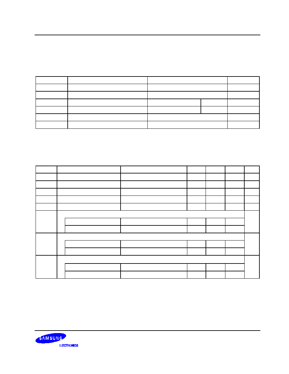
ELECTRICAL DATA
ABSOLUTE MAXIMUM RATINGS
Table 4. Absolute Maximum Rating
Symbol
Parameter
Rating
Unit
V
DD
1.8V Core DC Supply Voltage
2.4
V
V
DDP
3.3V I/O DC Supply Voltage
3.8
V
V
IN
DC Input Voltage
3.3 V Input buffer
3.8
V
V
OUT
DC Output Voltage
3.3 V Output buffer
3.8
V
I
latch
Latch-up Current
±
200
mA
T
STG
Storage Temperature
≠ 65 to 150
o
C
RECOMMENDED OPERATING CONDITIONS
Table 5. Recommended Operating Conditions
Symbol
Parameters
Condition
Min
Type
Max
Unit
V
DD
1.8V Core DC Supply Voltage Commercial
1.7
1.8
1.95
V
V
DDP
3.3V I/O DC Supply Voltage
Commercial
3.0
3.3
3.6
V
V
IN
DC Input Voltage
3.3V Input buffer
3.0
3.3
3.6
V
V
OUT
DC Output Voltage
3.3V Output buffer
3.0
3.3
3.6
V
T
OPR
Operating Temperature
Commercial
0
70
o
C
I
DD
Normal operating current (FCLK : HCLK : PCLK = 1: 1/2 : 1/4)
mA
1.8V core supply current
FCLK = 200MHz, V
DD
= 1.95V
≠
210
300
3.3V I/O supply current
FCLK = 200MHz, V
DDP
= 3.6V
≠
75
110
I
DD1
Idle mode current (FCLK : HCLK : PCLK = 1: 1/2 : 1/4)
mA
1.8V core supply current
FCLK = 200MHz, V
DD
= 1.95V
≠
75
110
3.3V I/O supply current
FCLK = 200MHz, V
DDP
= 3.6V
≠
15
30
I
DD2
Slow mode current (FCLK : HCLK : PCLK = 1: 1/2 : 1/2)
mA
1.8V core supply current
FCLK = 6MHz, V
DD
= 1.95V
≠
15
30
3.3V I/O supply current
FCLK = 6MHz, V
DDP
= 3.6V
≠
5
10

S3C2800 MICROCONTROLLER DATA SHEET
18
DC ELECTRICAL CHARACTERISTICS
Table 6. Normal I/O PAD DC Electrical Characteristics
(V
DD
= 1.8 V -0.1 V/+0.15 V, V
DDP
= 3.3 V
±
0.3 V, T
OPR
= 0 to 70
∞
C)
Symbol
Parameters
Condition
Min
Type
Max
Unit
V
IH
High level input voltage
V
LVCMOS interface
2.0
V
IL
Low level input voltage
V
LVCMOS interface
0.8
VT
Switching threshold
1.4
V
VT+
Schmitt trigger, positive-going threshold
CMOS
2.0
V
VT-
Schmitt trigger, negative-going threshold
CMOS
0.8
I
IH
High level input current
µ
A
Input buffer
V
IN
= V
DDP
-10
10
I
IL
Low level input current
µ
A
Input buffer
V
IN
= V
SS
-10
10
Input buffer with pull-up
-120
-66
-20
V
OH
High level output voltage
V
Type B4
I
OH
= -4 mA
2.4
Type B8
I
OH
= -8 mA
2.4
Type B12
I
OH
= -12 mA
2.4
V
OL
Low level output voltage
V
Type B4
I
OL
= 4 mA
0.4
Type B8
I
OL
= 8 mA
0.4
Type B12
I
OL
= 12 mA
0.4
C
IN
Input capacitance
Any Input and
Bi-directional
Buffers
4
pF
C
OUT
Output capacitance
Any Output
Buffers
4
pF

PRELIMINARY DATA SHEET S3C2800 MICROCONTROLLER
19
Table 7. PCI I/O PAD DC Electrical Characteristics
(V
DD
= 1.8 V -0.1 V/+0.15 V, V
DDP
= 3.3 V
±
0.3 V, T
OPR
= 0 to 70
∞
C)
Symbol
Parameters
Condition
Min
Type
Max
Unit
V
IH
High level input voltage
0.47V
DDP
V
DDP
+0.5
V
V
IL
Low level input voltage
-0.5
0.33V
DDP
V
I
I
Input Leakage Current
-10
10
µ
A
V
OH
High level output voltage
I
OH
= -500
µ
A
0.9V
DDP
V
V
OL
Low level output voltage
I
OL
= 1500
µ
A
0.1V
DDP
V

S3C2800 MICROCONTROLLER DATA SHEET
20
MECHANICAL DATA
PACKAGE DIMENSIONS
208-LQFP-2828
#208
28.00 ± 0.20
30.00 ± 0.30
28.00
± 0.20
30.00
± 0.30
0.10 MAX
0.127
+ 0.10
- 0.05
0~8
NOTE: Dimensions are in millimeters.
#1
0.50 °æ0.20
0.10 ± 0.05
1.40 ± 0.10
1.60 MAX
0.50
(1.25)
+ 0.10
- 0.05
0.20
0.08 MAX
Figure 3. 208-LQFP-2828 Package Dimensions