
�
�
The SAM47 instruction set is specifically designed to support the large register files typically founded in most
KS57-series microcontrollers. The SAM47 instruction set includes 1-bit, 4-bit, and 8-bit instructions for data
manipulation, logical and arithmetic operations, program control, and CPU control. I/O instructions for peripheral
hardware devices are flexible and easy to use. Symbolic hardware names can be substituted as the instruction
operand in place of the actual address. Other important features of the SAM47 instruction set include:
-- 1-byte referencing of long instructions (REF instruction)
-- Redundant instruction reduction (string effect)
-- Skip feature for ADC and SBC instructions
Instruction operands conform to the operand format defined for each instruction. Several instructions have multiple
operand formats.
Predefined values or labels can be used as instruction operands when addressing immediate data. Many of the
symbols for specific registers and flags may also be substituted as labels for operations such DA, mema, memb,
b, and so on. Using instruction labels can greatly simplify programming and debugging tasks.
�
In this section, the following SAM47 instruction set features are described in detail:
-- Instruction reference area
-- Instruction redundancy reduction
-- Flexible bit manipulation
-- ADC and SBC instruction skip condition
�
!"#$"#$%&&$
%&&'
(
)
*
+
�
INSTRUCTION REFERENCE AREA
Using the 1-byte REF (Reference) instruction, you can reference instructions stored in addresses 0020H-007FH of
program memory (the REF instruction look-up table). The location referenced by REF may contain either two 1-
byte instructions or a single 2-byte instruction. The starting address of the instruction being referenced must
always be an even number.
3-byte instructions such as JP or CALL may also be referenced using REF. To reference these 3-byte instructions,
the 2-byte pseudo commands TJP and TCALL must be written in the reference instead of JP and CALL.
The PC is not incremented when a REF instruction is executed. After it executes, the program's instruction
execution sequence resumes at the address immediately following the REF instruction. By using REF instructions
to execute instructions larger than one byte, as well as branches and subroutines, you can reduce program size.
To summarize, the REF instruction can be used in three ways:
-- Using the 1-byte REF instruction to execute one 2-byte or two 1-byte instructions;
-- Branching to any location by referencing a branch address that is stored in the look-up table;
-- Calling subroutines at any location by referencing a call address that is stored in the look-up table.
If necessary, a REF instruction can be circumvented by means of a skip operation prior to the REF in the
execution sequence. In addition, the instruction immediately following a REF can also be skipped by using an
appropriate reference instruction or instructions.
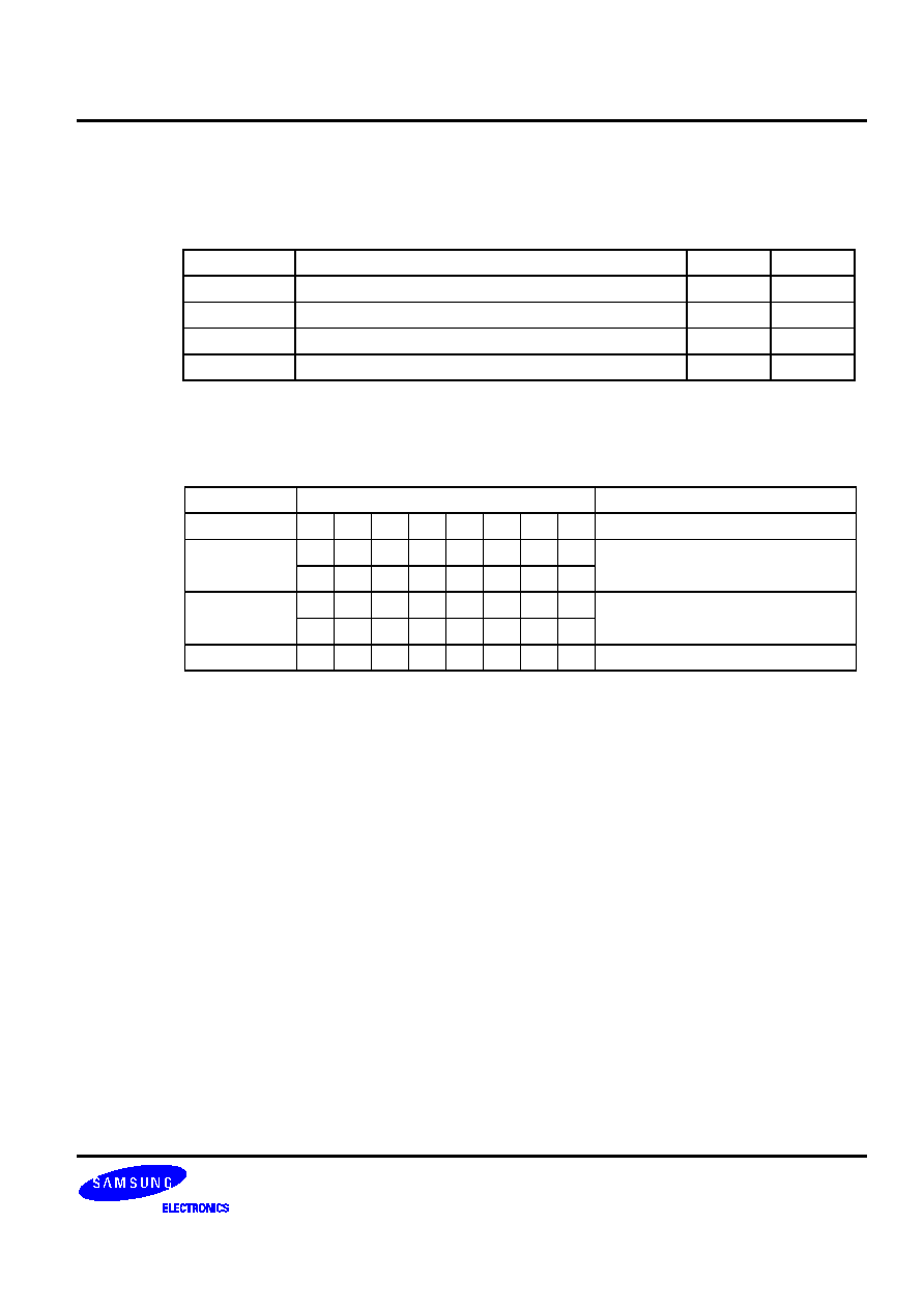
Two-byte instruction can be referenced by using a REF instruction (An exception is XCH A, DA). If the MSB value
of the first one-byte instruction in the reference area is "0", the instruction cannot be referenced by a REF
instruction. Therefore, if you use REF to reference two 1-byte instruction stored in the reference area, specific
combinations must be used for the first and second 1-byte instruction.
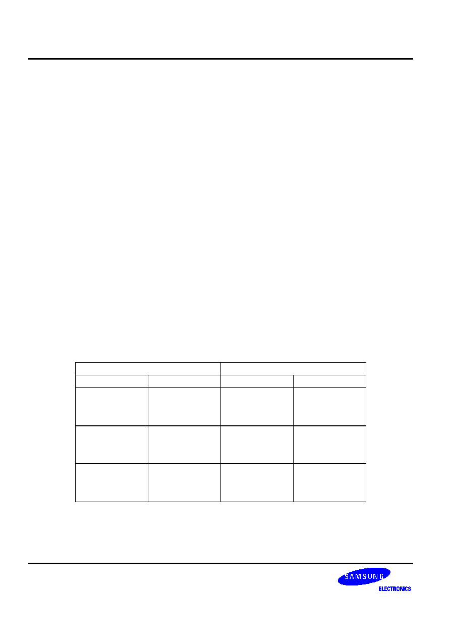
These combination examples are described in Table 5-1.
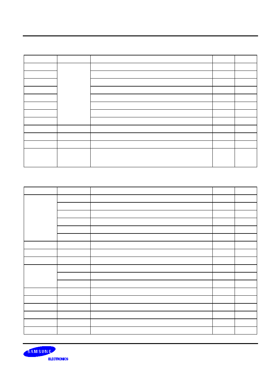
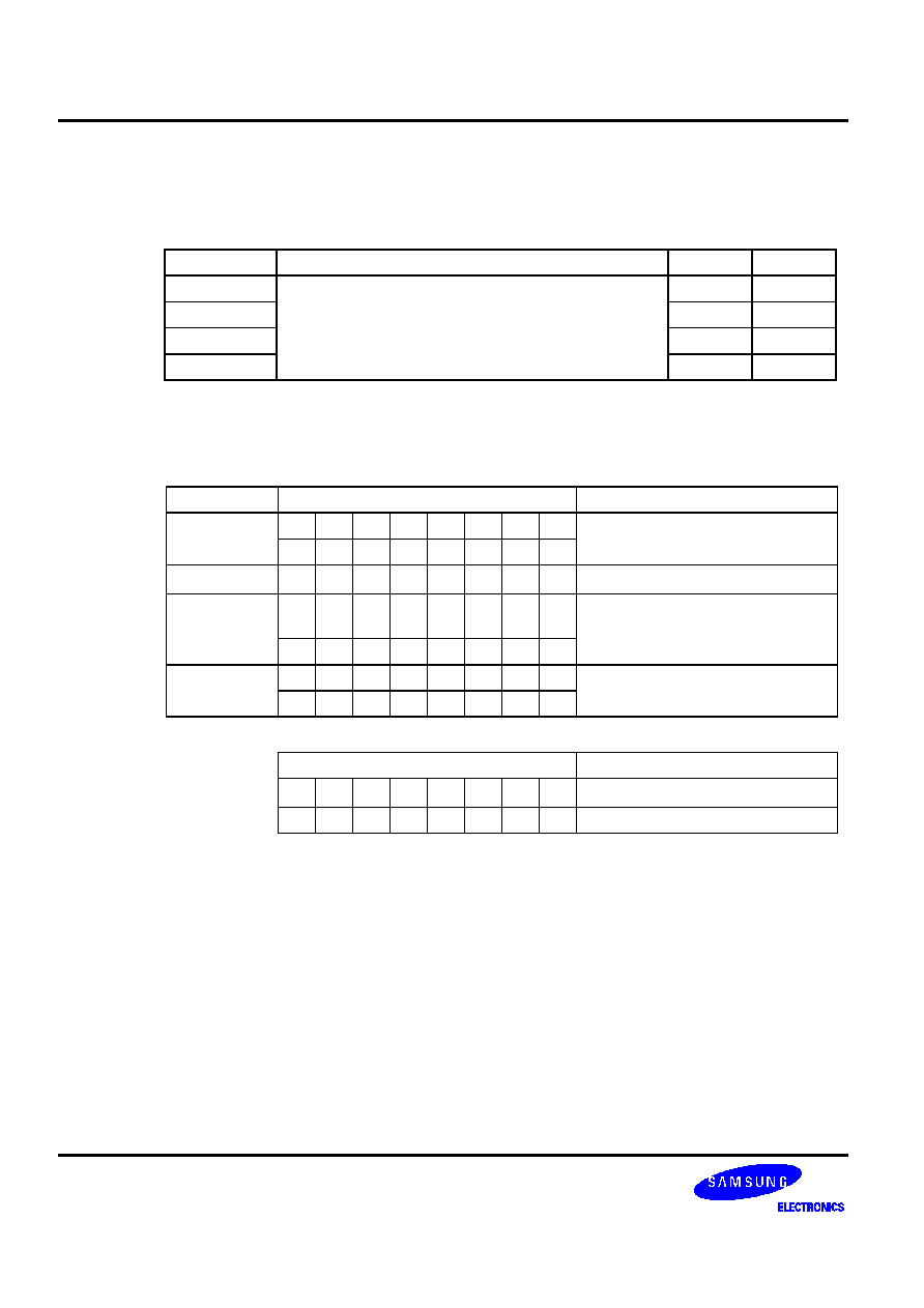
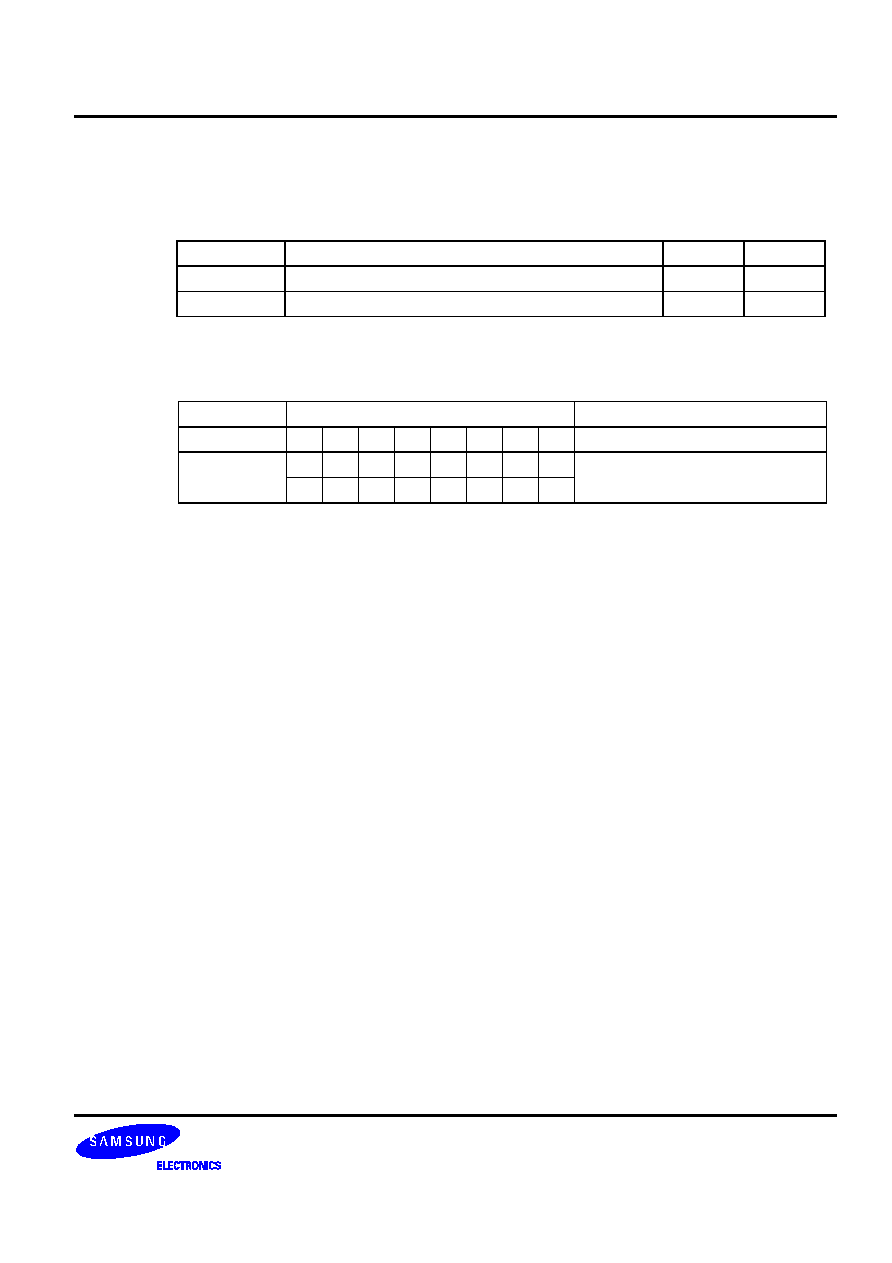
Table 5-1. Valid 1-Byte Instruction Combinations for REF Look-Ups
First 1-Byte Instruction
Second 1-Byte Instruction
Instruction Operand Instruction Operand
LD A,
#im
INCS
R
INCS
RRb
DECS
R
LD A,
@RRa
INCS
R
INCS
RRb
DECS
R
LD @HL,
A
INCS
R
INCS
RRb
DECS
R
,*
-./

�
REDUCING INSTRUCTION REDUNDANCY
When redundant instructions such as LD A,#im and LD EA,#imm are used consecutively in a program sequence,
only the first instruction is executed. The redundant instructions which follow are ignored, that is, they are handled
like a NOP instruction. When LD HL,#imm instructions are used consecutively, redundant instructions are also
ignored.
In the following example, only the 'LD A, #im' instruction will be executed. The 8-bit load instruction which follows it
is interpreted as redundant and is ignored:
LD
A,#im
; Load 4-bit immediate data (#im) to accumulator
LD
EA,#imm
; Load 8-bit immediate data (#imm) to extended
;
accumulator
In this example, the statements 'LD A,#2H' and 'LD A,#3H' are ignored:
BITR
EMB
LD
A,#1H
; Execute instruction
LD
A,#2H
; Ignore, redundant instruction
LD
A,#3H
; Ignore, redundant instruction
LD
23H,A
; Execute instruction, 023H
#1H
If consecutive LD HL, #imm instructions (load 8-bit immediate data to the 8-bit memory pointer pair, HL) are
detected, only the first LD is executed and the LDs which immediately follow are ignored. For example,
LD
HL,#10H
; HL
10H
LD
HL,#20H
; Ignore, redundant instruction
LD
A,#3H
; A
3H
LD
EA,#35H
; Ignore, redundant instruction
LD
@HL,A
; (10H)
3H
If an instruction reference with a REF instruction has a redundancy effect, the following conditions apply:
-- If the instruction preceding the REF has a redundancy effect, this effect is cancelled and the referenced
instruction is not skipped.
-- If the instruction following the REF has a redundancy effect, the instruction following the REF is skipped.
PROGRAMMING TIP -- Example of the Instruction Redundancy Effect
ORG
0020H
ABC
LD
EA,#30H
; Stored in REF instruction reference area
ORG
0080H
LD
EA,#40H
; Redundancy effect is encountered
REF
ABC
; No skip (EA
#30H)
REF
ABC
;
EA
#30H
LD
EA,#50H
;
Skip
�
FLEXIBLE BIT MANIPULATION
In addition to normal bit manipulation instructions like set and clear, the SAM47 instruction set can also perform bit
tests, bit transfers, and bit Boolean operations. Bits can also be addressed and manipulated by special bit
addressing modes. Three types of bit addressing are supported:
-- mema.b
-- memb.@L
-- @H+DA.b
The parameters of these bit addressing modes are described in more detail in Table 5-2.
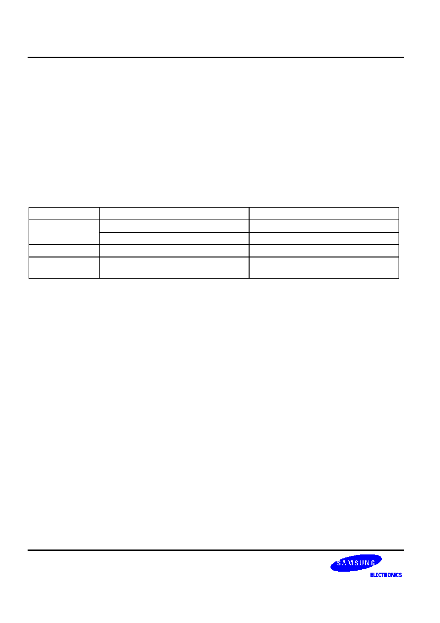
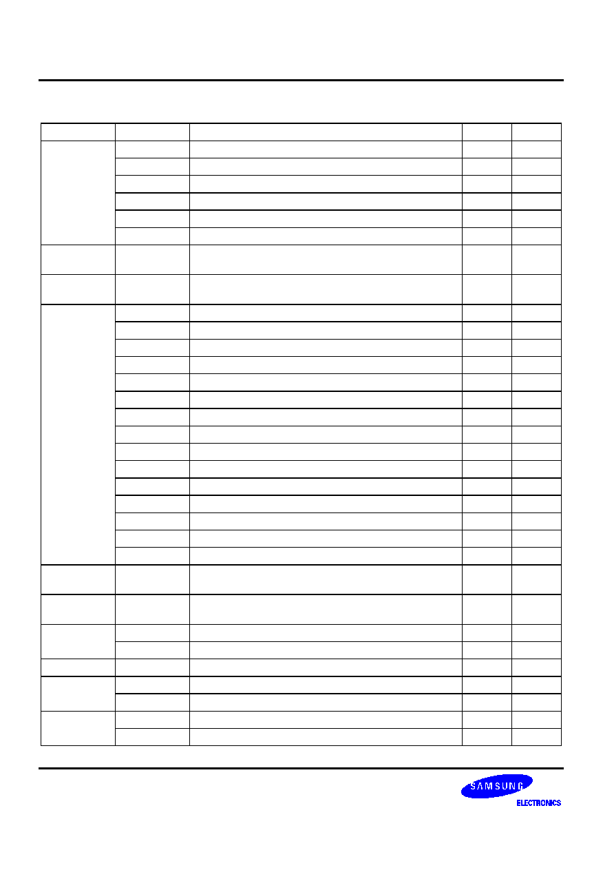
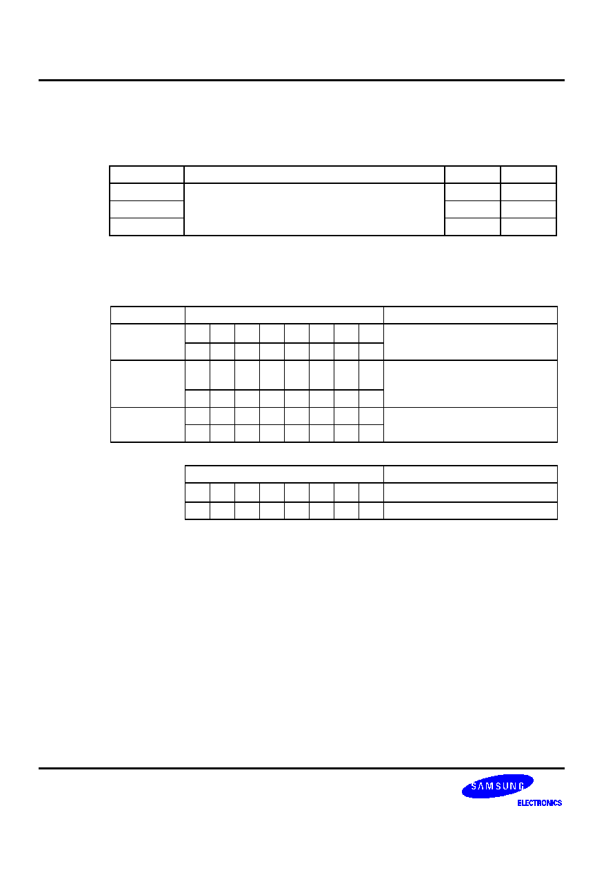
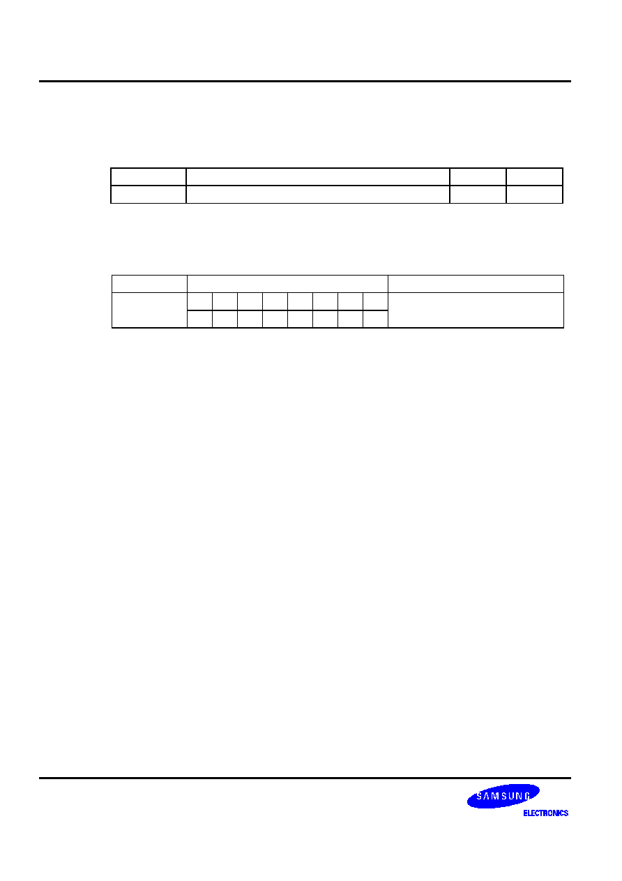
Table 5-2. Bit Addressing Modes and Parameters
Addressing Mode
Addressable Peripherals
Address Range
mema.b
ERB, EMB, IS1, IS0, IEx, IRQx
FB0H-FBFH
Ports
FF0H-FFFH
memb.@L
BSCx, Ports
FC0H-FFFH
@H+DA.b
All bit-manipulatable peripheral hardware
All bits of the memory bank specified by
EMB and SMB that are bit-manipulatable
,
0
*%
�
��
The following instructions have a skip function when an overflow or borrow occurs:
XCHI INCS
XCHD DECS
LDI ADS
LDD SBS
If there is an overflow or borrow from the result of an increment or decrement, a skip signal is generated and a
skip is executed. However, the carry flag value is unaffected.
The instructions BTST, BTSF, and CPSE also generate a skip signal and execute a skip when they meet a skip
condition, and the carry flag value is also unaffected.
�
INSTRUCTIONS WHICH AFFECT THE CARRY FLAG
The only instructions which do not generate a skip signal, but which do affect the carry flag are as follows:
ADC LDB
C,(operand)
SBC BAND
C,(operand)
SCF BOR
C,(operand)
RCF BXOR
C,(operand)
CCF IRET
RRC
ADC AND SBC INSTRUCTION SKIP CONDITIONS
The instructions 'ADC A,@HL' and 'SBC A,@HL' can generate a skip signal, and set or clear the carry flag, when
they are executed in combination with the instruction 'ADS A,#im'.
If an 'ADS A,#im' instruction immediately follows an 'ADC A,@HL' or 'SBC A,@HL' instruction in a program
sequence, the ADS instruction does not skip the instruction following ADS, even if it has a skip function. If,
however, an 'ADC A,@HL' or 'SBC A,@HL' instruction is immediately followed by an 'ADS A,#im' instruction, the
ADC (or SBC) skips on overflow (or if there is no borrow) to the instruction immediately following the ADS, and
program execution continues. Table 5-3 contains additional information and examples of the 'ADC A,@HL' and
'SBC A,@HL' skip feature.
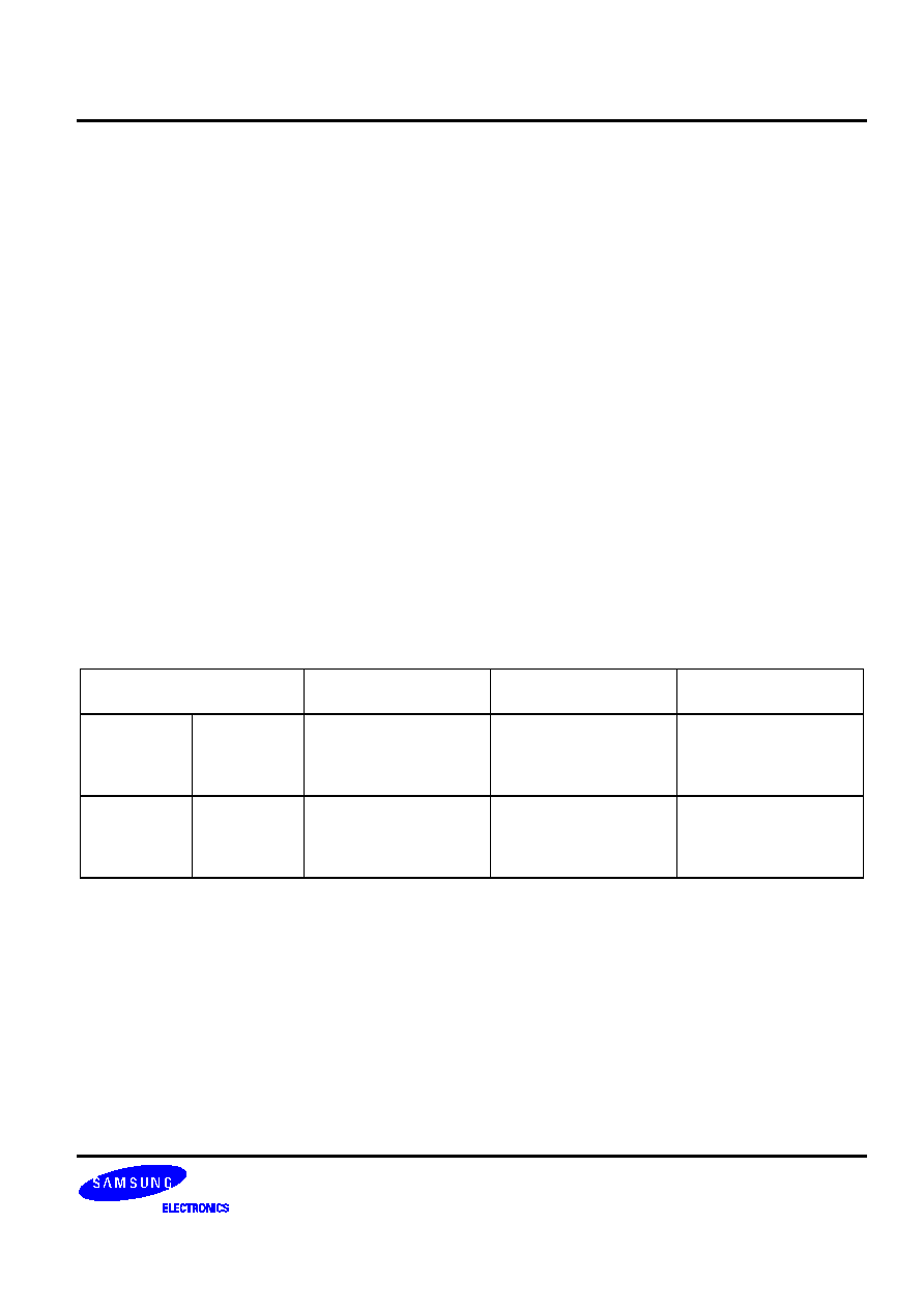
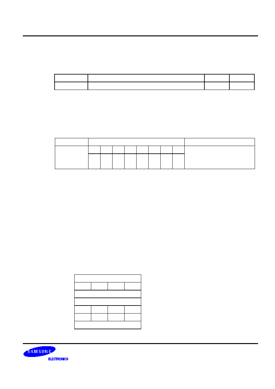
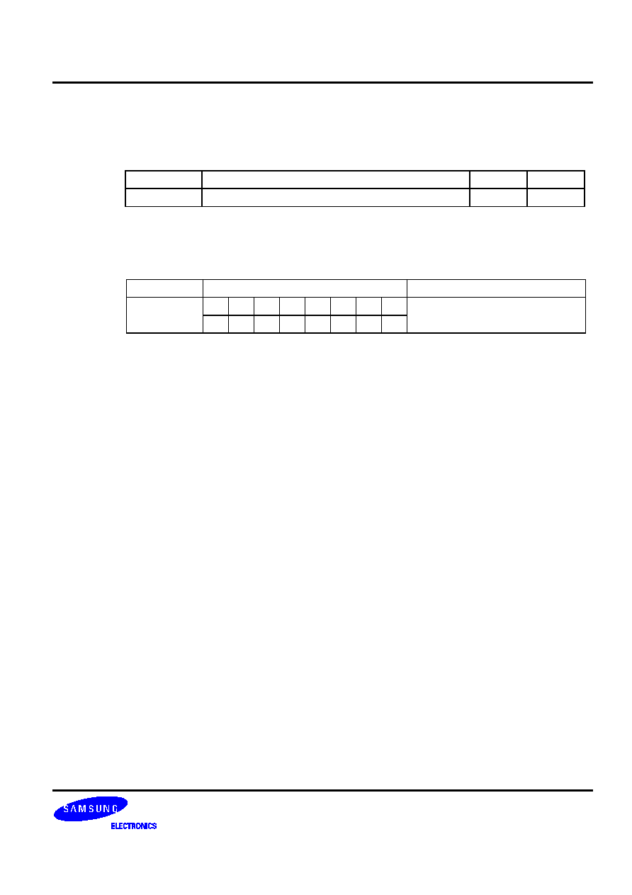
Table 5-3. Skip Conditions for ADC and SBC Instructions
Sample
Instruction Sequences
If the result of
instruction 1 is:
Then, the execution
sequence is:
Reason
ADC A,@HL
ADS A,#im
xxx
xxx
1
2
3
4
Overflow
No overflow
1, 3, 4
1, 2, 3, 4
ADS cannot skip
instruction 3, even if it
has a skip function.
SBC A,@HL
ADS A,#im
xxx
xxx
1
2
3
4
Borrow
No borrow
1, 2, 3, 4
1, 3, 4
ADS cannot skip
instruction 3, even if it
has a skip function.
�
�
Table 5-4. Data Type Symbols
Symbol Data
Type
d Immediate
data
a Address
data
b Bit
data
r Register
data
f Flag
data
i
Indirect addressing data
t
memc
�
0.5 immediate data
Table 5-5. Register Identifiers
Full Register Name
ID
4-bit accumulator
A
4-bit working registers
E, L, H, X, W,
Z, Y
8-bit extended accumulator
EA
8-bit memory pointer
HL
8-bit working registers
WX, YZ, WL
Select register bank 'n'
SRB n
Select memory bank 'n'
SMB n
Carry flag
C
Program status word
PSW
Port 'n'
Pn
'm'-th bit of port 'n'
Pn.m
Interrupt priority register
IPR
Enable memory bank flag
EMB
Enable register bank flag
ERB
Table 5-6. Instruction Operand Notation
Symbol Definition
DA Direct
address
@
Indirect address prefix
src Source
operand
dst Destination
operand
(R)
Contents of register R
.b Bit
location
im
4-bit immediate data (number)
imm
8-bit immediate data (number)
#
Immediate data prefix
ADR
000H-3FFFH immediate address
ADRn
'n' bit address
R
A, E, L, H, X, W, Z, Y
Ra
E, L, H, X, W, Z, Y
RR
EA, HL, WX, YZ
RRa
HL, WX, WL
RRb
HL, WX, YZ
RRc WX,
WL
mema FB0H-FBFH,
FF0H-FFFH
memb FC0H-FFFH
memc
Code direct addressing:
0020H-007FH
SB
Select bank register (8 bits)
XOR Logical
exclusive-OR
OR Logical
OR
AND Logical
AND
[(RR)]
Contents addressed by RR

�
�
Table 5-7. Opcode Definitions (Direct)
Register r2 r1 r0
A
0 0 0
E
0 0 1
L
0 1 0
H
0 1 1
X
1 0 0
W
1 0 1
Z
1 1 0
Y
1 1 1
EA
0 0 0
HL
0 1 0
WX
1 0 0
YZ
1 1 0
12
Table 5-8. Opcode Definitions (Indirect)
Register i2 i1 i0
@HL
1 0 1
@WX
1 1 0
@WL
1 1 1
12
��
���
A machine cycle is defined as one cycle of the selected CPU clock. Three different clock rates can be selected
using the PCON register.
In this document, the letter 'S' is used in tables when describing the number of additional machine cycles required
for an instruction to execute, given that the instruction has a skip function ('S' = skip). The addition number of
machine cycles that will be required to perform the skip usually depends on the size of the instruction being
skipped -- whether it is a 1-byte, 2-byte, or 3-byte instruction. A skip is also executed for SMB and SRB
instructions.
The values in additional machine cycles for 'S' for the three cases in which skip conditions occur are as follows:
Case 1: No skip
S = 0 cycles
Case 2: Skip is 1-byte or 2-byte instruction
S = 1 cycle
Case 3: Skip is 3-byte instruction
S = 2 cycles
, 34
)

�
This section contains a high-level summary of the SAM47 instruction set in table format. The tables are designed
to familiarize you with the range of instructions that are available in each instruction category.
These tables are a useful quick-reference resource when writing application programs.
If you are reading this user's manual for the first time, however, you may want to scan this detailed information
briefly, and then return to it later on. The following information is provided for each instruction:
-- Instruction name
-- Operand(s)
-- Brief operation description
-- Number of bytes of the instruction and operand(s)
-- Number of machine cycles required to execute the instruction
The tables in this section are arranged according to the following instruction categories:
-- CPU control instructions
-- Program control instructions
-- Data transfer instructions
-- Logic instructions
-- Arithmetic instructions
-- Bit manipulation instructions
�
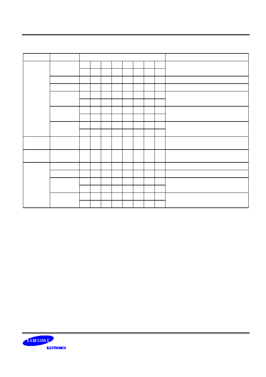
Table 5-9. CPU Control Instructions -- High-Level Summary
Name Operand
Operation
Description
Bytes
Cycles
SCF
�
Set carry flag to logic one
1
1
RCF
Reset carry flag to logic zero
1
1
CCF
Complement carry flag
1
1
EI
Enable all interrupts
2
2
DI
Disable all interrupts
2
2
IDLE
Engage CPU idle mode
2
2
STOP
Engage CPU stop mode
2
2
NOP
No
operation
1
1
SMB
n
Select memory bank
2
2
SRB
n
Select register bank
2
2
REF memc
Reference
code
1
3
VENTn EMB
(0,1)
ERB (0,1)
ADR
Load enable memory bank flag (EMB) and the enable
register bank flag (ERB) and program counter to vector
address, then branch to the corresponding location
2 2
Table 5-10. Program Control Instructions -- High-Level Summary
Name Operand
Operation
Description
Bytes
Cycles
CPSE
R,#im
Compare and skip if register equals #im
2
2 + S
@HL,#im
Compare and skip if indirect data memory equals #im
2
2 + S
A,R
Compare and skip if A equals R
2
2 + S
A,@HL
Compare and skip if A equals indirect data memory
1
1 + S
EA,@HL
Compare and skip if EA equals indirect data memory
2
2 + S
EA,RR
Compare and skip if EA equals RR
2
2 + S
LJP
ADR
Long jump to direct address (15 bits)
3
3
JP
ADR
Jump to direct address (14 bits)
3
3
JPS
ADR
Jump direct in page (12 bits)
2
2
JR
#im
Jump to immediate address
1
2
@WX
Branch relative to WX register
2
3
@EA
Branch relative to EA
2
3
LCALL
ADR
Long call direct in page (15 bits)
3
4
CALL
ADR
Call direct in page (14 bits)
3
4
CALLS
ADR
Call direct in page (11 bits)
2
3
RET
�
Return from subroutine
1
3
IRET
�
Return from interrupt
1
3
SRET
�
Return from subroutine and skip
1
3 + S
�
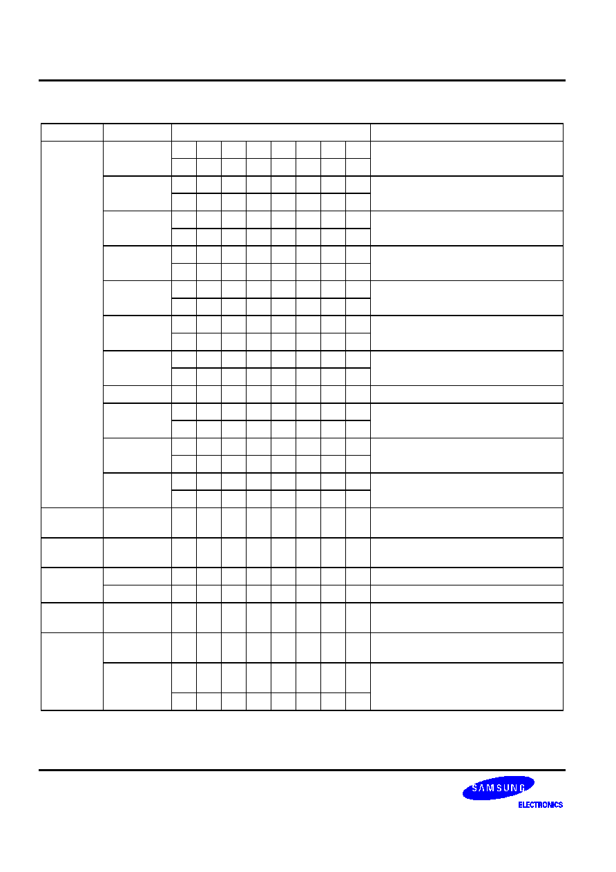
Table 5-11. Data Transfer Instructions -- High-Level Summary
Name Operand
Operation
Description
Bytes
Cycles
XCH
A,DA
Exchange A and direct data memory contents
2
2
A,Ra
Exchange A and register (Ra) contents
1
1
A,@Rra
Exchange A and indirect data memory
1
1
EA,DA
Exchange EA and direct data memory contents
2
2
EA,RRb
Exchange EA and register pair (RRb) contents
2
2
EA,@HL
Exchange EA and indirect data memory contents
2
2
XCHI
A,@HL
Exchange A and indirect data memory contents;
increment contents of register L and skip on carry
1
2 + S
XCHD
A,@HL
Exchange A and indirect data memory contents;
decrement contents of register L and skip on carry
1
2 + S
LD
A,#im
Load 4-bit immediate data to A
1
1
A,@Rra
Load indirect data memory contents to A
1
1
A,DA
Load direct data memory contents to A
2
2
A,Ra
Load register contents to A
2
2
Ra,#im
Load 4-bit immediate data to register
2
2
RR,#imm
Load 8-bit immediate data to register
2
2
DA,A
Load contents of A to direct data memory
2
2
Ra,A
Load contents of A to register
2
2
EA,@HL
Load indirect data memory contents to EA
2
2
EA,DA
Load direct data memory contents to EA
2
2
EA,RRb
Load register contents to EA
2
2
@HL,A
Load contents of A to indirect data memory
1
1
DA,EA
Load contents of EA to data memory
2
2
RRb,EA
Load contents of EA to register
2
2
@HL,EA
Load contents of EA to indirect data memory
2
2
LDI
A,@HL
Load indirect data memory to A; increment register L
contents and skip on carry
1
2 + S
LDD
A,@HL
Load indirect data memory contents to A; decrement
register L contents and skip on carry
1
2 + S
LDC
EA,@WX
Load code byte from WX to EA
1
3
EA,@EA
Load code byte from EA to EA
1
3
RRC
A
Rotate right through carry bit
1
1
PUSH
RR
Push register pair onto stack
1
1
SB
Push SMB and SRB values onto stack
2
2
POP
RR
Pop to register pair from stack
1
1
SB
Pop SMB and SRB values from stack
2
2

�
Table 5-12. Logic Instructions -- High-Level Summary
Name Operand
Operation
Description
Bytes
Cycles
AND
A,#im
Logical-AND A immediate data to A
2
2
A,@HL
Logical-AND A indirect data memory to A
1
1
EA,RR
Logical-AND register pair (RR) to EA
2
2
RRb,EA
Logical-AND EA to register pair (RRb)
2
2
OR
A, #im
Logical-OR immediate data to A
2
2
A, @HL
Logical-OR indirect data memory contents to A
1
1
EA,RR
Logical-OR double register to EA
2
2
RRb,EA
Logical-OR EA to double register
2
2
XOR
A,#im
Exclusive-OR immediate data to A
2
2
A,@HL
Exclusive-OR indirect data memory to A
1
1
EA,RR
Exclusive-OR register pair (RR) to EA
2
2
RRb,EA
Exclusive-OR register pair (RRb) to EA
2
2
COM
A
Complement accumulator (A)
2
2
Table 5-13. Arithmetic Instructions -- High-Level Summary
Name Operand
Operation
Description
Bytes
Cycles
ADC
A,@HL
Add indirect data memory to A with carry
1
1
EA,RR
Add register pair (RR) to EA with carry
2
2
RRb,EA
Add EA to register pair (RRb) with carry
2
2
ADS
A, #im
Add 4-bit immediate data to A and skip on carry
1
1 + S
EA,#imm
Add 8-bit immediate data to EA and skip on carry
2
2 + S
A,@HL
Add indirect data memory to A and skip on carry
1
1 + S
EA,RR
Add register pair (RR) contents to EA and skip on carry
2
2 + S
RRb,EA
Add EA to register pair (RRb) and skip on carry
2
2 + S
SBC
A,@HL
Subtract indirect data memory from A with carry
1
1
EA,RR
Subtract register pair (RR) from EA with carry
2
2
RRb,EA
Subtract EA from register pair (RRb) with carry
2
2
SBS
A,@HL
Subtract indirect data memory from A; skip on borrow
1
1 + S
EA,RR
Subtract register pair (RR) from EA; skip on borrow
2
2 + S
RRb,EA
Subtract EA from register pair (RRb); skip on borrow
2
2 + S
DECS
R
Decrement register �; skip on borrow
1
1 + S
RR
Decrement register pair (RR); skip on borrow
2
2 + S
INCS
R
Increment register �; skip on carry
1
1 + S
DA
Increment direct data memory; skip on carry
2
2 + S
@HL
Increment indirect data memory; skip on carry
2
2 + S
RRb
Increment register pair (RRb); skip on carry
1
1 + S
�
Table 5-14. Bit Manipulation Instructions -- High-Level Summary
Name Operand
Operation
Description
Bytes
Cycles
BTST
C
Test specified bit and skip if carry flag is set
1
1 + S
DA.b
Test specified bit and skip if memory bit is set
2
2 + S
mema.b
memb.@L
@H+DA.b
BTSF
DA.b
Test specified memory bit and skip if bit equals "0"
mema.b
memb.@L
@H+DA.b
BTSTZ
mema.b
Test specified bit; skip and clear if memory bit is set
memb.@L
@H+DA.b
BITS
DA.b
Set specified memory bit
2
2
mema.b
memb.@L
@H+DA.b
BITR
DA.b
Clear specified memory bit to logic zero
mema.b
memb.@L
@H+DA.b
BAND
C,mema.b
Logical-AND carry flag with specified memory bit
C,memb.@L
C,@H+DA.b
BOR
C,mema.b
Logical-OR carry with specified memory bit
C,memb.@L
C,@H+DA.b
BXOR
C,mema.b
Exclusive-OR carry with specified memory bit
C,memb.@L
C,@H+DA.b
LDB
mema.b,C
Load carry bit to a specified memory bit
memb.@L,C
Load carry bit to a specified indirect memory bit
@H+DA.b,C
C,mema.b
Load specified memory bit to carry bit
C,memb.@L
Load specified indirect memory bit to carry bit
C,@H+DA.b

�
�
This section contains binary code values and operation notation for each instruction in the SAM47 instruction set in
an easy-to-read, tabular format. It is intended to be used as a quick-reference source for programmers who are
experienced with the SAM47 instruction set. The same binary values and notation are also included in the detailed
descriptions of individual instructions later in Section 5.
If you are reading this user's manual for the first time, please just scan this very detailed information briefly. Most
of the general information you will need to write application programs can be found in the high-level summary
tables in the previous section. The following information is provided for each instruction:
-- Instruction name
-- Operand(s)
-- Binary values
-- Operation notation
The tables in this section are arranged according to the following instruction categories:
-- CPU control instructions
-- Program control instructions
-- Data transfer instructions
-- Logic instructions
-- Arithmetic instructions
-- Bit manipulation instructions

�
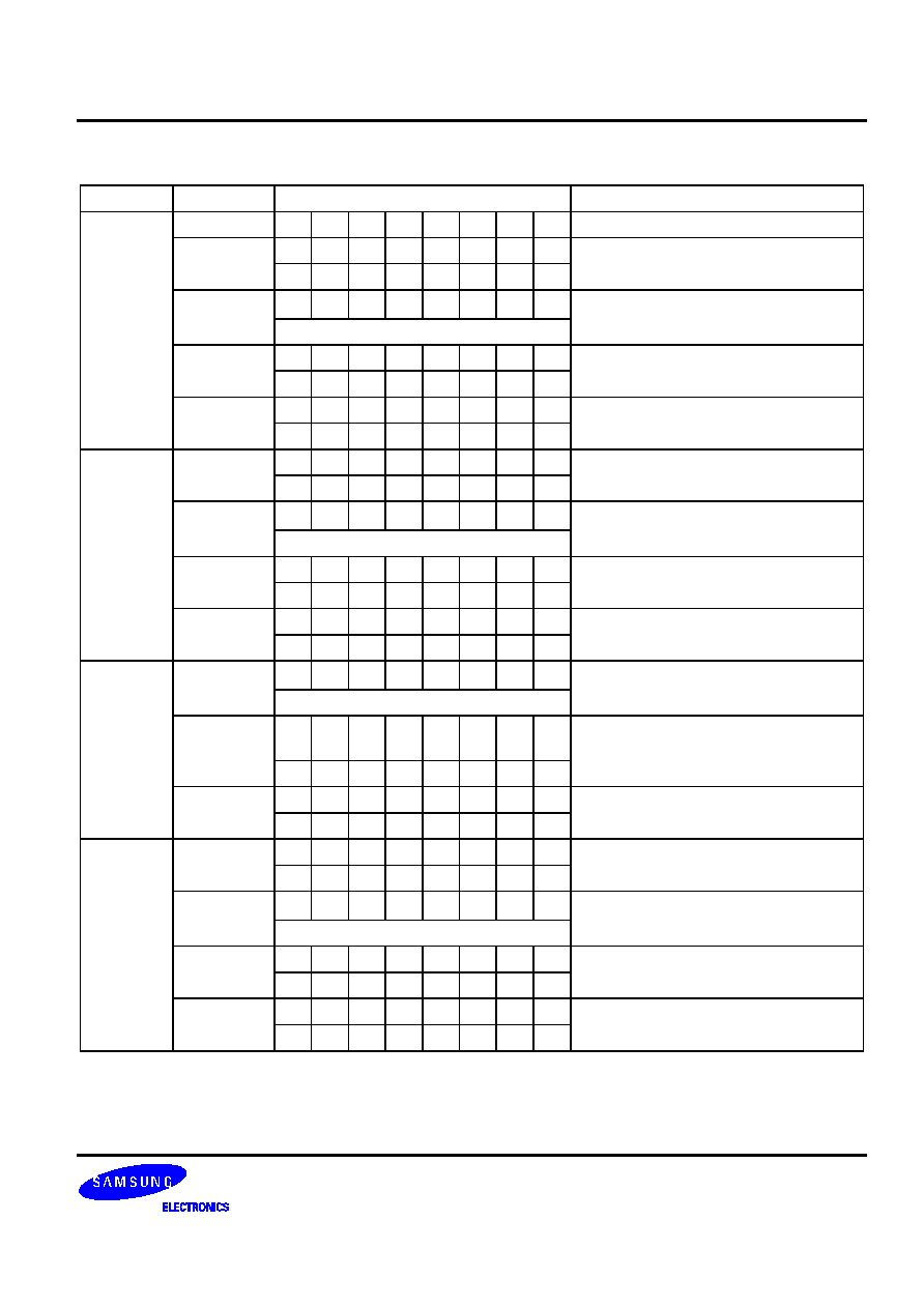
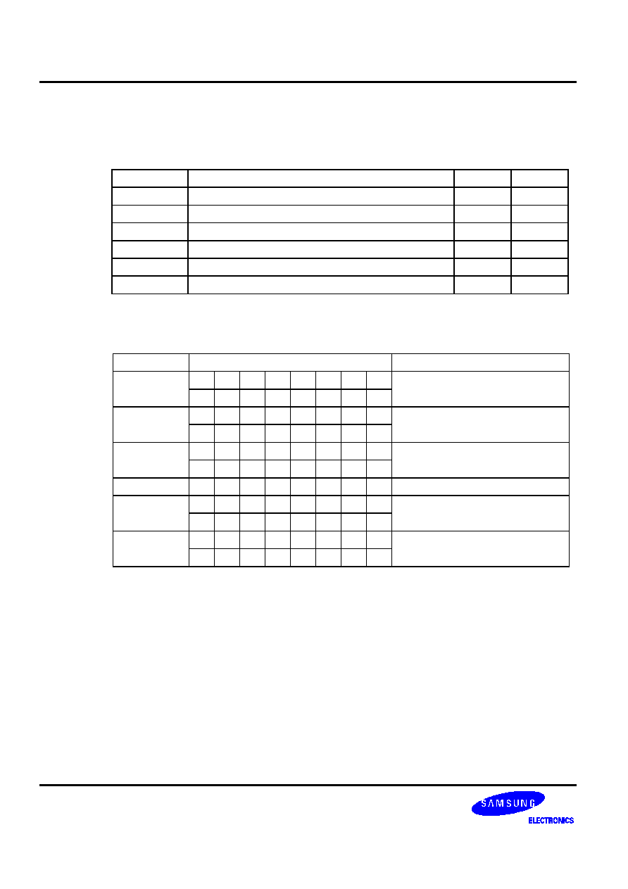
Table 5-15. CPU Control Instructions -- Binary Code Summary
Name
Operand
Binary Code
Operation Notation
SCF
.
.
C
1
RCF
.
.
.
C
0
CCF
.
.
.
C
EI
IME
1
.
.
.
.
DI
.
IME
0
.
.
.
.
IDLE
PCON.2
1
.
.
.
.
STOP
PCON.3
1
.
.
.
NOP
.
.
.
.
.
.
No operation
SMB n
.
.
SMB
n (n = 0, ... ,15)
.
.
.
+ ( .
SRB n
.
.
SRB
n (n = 0, 1, 2, 3)
.
.
.
.
.
REF memc
5
6
+
(
.
PC13-0
memc.7-4, memc.3-0 < 1
VENTn EMB
(0,1)
ERB (0,1)
ADR
3
*
3
*
+
(
.
7
8
ROM (2 x n) 7-6
EMB, ERB
ROM (2 x n) 5-4
PC13-12
ROM (2 x n) 3-0
PC11-8
ROM (2 x n + 1) 7-0
PC7-0
(n = 0, 1, 2, 3, 4, 5, 6, 7)
5
6
+
(
.

�
Table 5-16. Program Control Instructions -- Binary Code Summary
Name
Operand
Binary Code
Operation Notation
CPSE R,#im
.
.
.
Skip if R = im
+ ( .
.
(
.
@HL,#im
.
.
Skip if (HL) = im
.
+ ( .
A,R
.
.
Skip if A = R
.
.
(
.
A,@HL
.
.
.
.
.
Skip if A = (HL)
EA,@HL
.
.
.
Skip if A = (HL), E = (HL+1)
.
.
.
.
.
.
EA,RR
.
.
.
Skip if EA = RR
.
(
.
LJP ADR
.
.
.
.
PC14-0
ADR14-0
.
+
(
.
7
8
5
6
+
(
.
JP ADR
.
.
PC13-0
ADR13-0
.
.
+
(
.
7
8
5
6
+
(
.
JPS ADR
.
.
.
7
8
PC14-0
PC14-12 + ADR11-0
5
6
+
(
.
JR
#im
PC13-0
ADR (PC-15 to PC+16)
@WX
.
.
PC13-0
PC13-8 + (WX)
.
.
.
.
.
@EA
.
.
PC13-0
PC13-8 + (EA)
.
.
.
.
.
.
LCALL ADR
.
.
.
[(SP-1) (SP-2)]
EMB, ERB
.
+
(
.
7
8
[(SP-3) (SP-4)]
PC7-0
5
6
+
(
.
[(SP-5) (SP-6)]
PC14-8
CALL ADR
.
.
[(SP-1) (SP-2)]
EMB, ERB
.
+
(
.
7
8
[(SP-3) (SP-4)]
PC7-0
5
6
+
(
.
[(SP-5) (SP-6)]
PC13-8
CALLS ADR
.
.
7
8
[(SP-1) (SP-2)]
EMB, ERB
5
6
+
(
.
[(SP-3) (SP-4)]
PC7-0
[(SP-5) (SP-6)]
PC14-8
�
First
Byte
Condition
JR #im
.
.
.
+
(
.
PC
PC+2 to PC+16
.
.
.
.
+
(
.
PC
PC-1 to PC-15
Table 5-16. Program Control Instructions -- Binary Code Summary (Continued)
Name
Operand
Binary Code
Operation Notation
RET �
.
.
.
.
PC14-8
(SP + 1) (SP)
PC7-0
(SP + 3) (SP + 2)
EMB,ERB
(SP + 5) (SP + 4)
SP
SP + 6
IRET �
.
.
.
PC14-8
(SP + 1) (SP)
PC7-0
(SP + 3) (SP + 2)
PSW
(SP + 5) (SP + 4)
SP
SP + 6
SRET �
.
.
.
PC14-8
(SP + 1) (SP)
PC7-0
(SP + 3) (SP + 2)
EMB,ERB
(SP + 5) (SP + 4)
SP
SP + 6
�
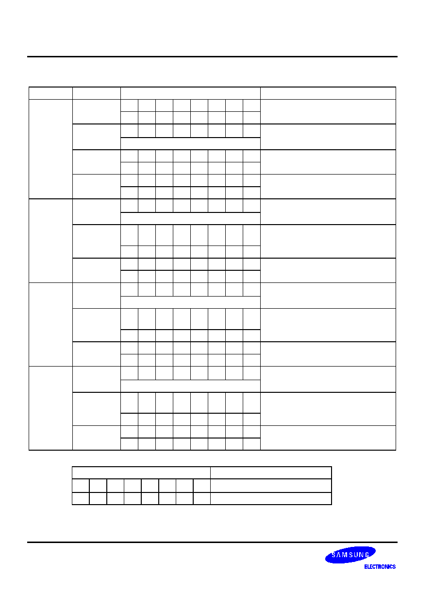
Table 5-17. Data Transfer Instructions -- Binary Code Summary
Name
Operand
Binary Code
Operation Notation
XCH A,DA
.
.
.
A
DA
5
6
+
(
.
A,Ra
.
.
(
.
A
Ra
A,@RRa
.
(
.
A
(RRa)
EA,DA
.
.
A
DA,E
DA + 1
5
6
+
(
.
EA,RRb
.
.
.
EA
RRb
.
.
(
.
EA,@HL
.
.
.
A
(HL), E
(HL + 1)
.
.
.
.
.
.
.
XCHI A,@HL
.
.
.
A
(HL), then L
L+1;
skip if L = 0H
XCHD A,@HL
.
.
A
(HL), then L
L-1;
skip if L = 0FH
LD A,#im
.
+ ( .
A
im
A,@RRa
.
.
.
(
.
A
(RRa)
A,DA
.
.
.
.
.
A
DA
5
6
+
(
.
A,Ra
.
.
A
Ra
.
.
.
.
(
.
�
Table 5-17. Data Transfer Instructions -- Binary Code Summary (Continued)
Name
Operand
Binary Code
Operation Notation
LD Ra,#im
.
.
.
Ra
im
+ ( .
(
.
RR,#imm
.
.
.
.
(
RR
imm
5 6 + ( .
DA,A
.
.
.
.
.
DA
A
5
6
+
(
.
Ra,A
.
.
Ra
A
.
.
.
.
.
(
.
EA,@HL
.
.
.
A
(HL), E
(HL + 1)
.
.
.
.
.
.
.
EA,DA
.
.
.
A
DA, E
DA + 1
5
6
+
(
.
EA,RRb
.
.
.
EA
RRb
(
.
@HL,A
.
.
.
.
.
(HL)
A
DA,EA
.
.
.
DA
A, DA + 1
E
5
6
+
(
.
RRb,EA
.
.
.
RRb
EA
.
(
.
@HL,EA
.
.
.
(HL)
A, (HL + 1)
E
.
.
.
.
.
.
.
.
LDI A,@HL
.
.
.
.
.
A
(HL), then L
L+1;
skip if L = 0H
LDD A,@HL
.
.
.
.
A
(HL), then L
L-1;
skip if L = 0FH
LDC EA,@WX
.
.
.
.
EA
[PC14-8 + (WX)]
EA,@EA
.
.
.
.
.
EA
[PC14-8 + (EA)]
RRC A
.
.
.
.
.
.
C
A.0, A3
C
A.n-1
A.n (n = 1, 2, 3)
PUSH
RR
.
.
.
(
((SP-1)) ((SP-2))
(RR),
(SP)
(SP)-2
SB
.
.
((SP-1))
(SMB), ((SP-2))
(SRB),
(SP)
(SP)-2
.
.
.

�
Table 5-17. Data Transfer Instructions -- Binary Code Summary (Concluded)
Name
Operand
Binary Code
Operation Notation
POP
RR
.
.
.
(
.
RR
(SP), RR
(SP + 1)
SP
SP + 2
SB
.
.
(SRB)
(SP), SMB
(SP + 1),
SP
SP + 2
.
.
.
.
Table 5-18. Logic Instructions -- Binary Code Summary
Name
Operand
Binary Code
Operation Notation
AND A,#im
.
.
A
A AND im
.
.
.
+ ( .
A,@HL
.
.
.
.
A
A AND (HL)
EA,RR
.
.
.
EA
EA AND RR
.
.
.
(
.
RRb,EA
.
.
.
RRb
RRb AND EA
.
.
.
.
(
.
OR A,
#im
.
.
A
A OR im
.
.
.
+ ( .
A,
@HL
.
.
.
.
A
A OR (HL)
EA,RR
.
.
.
EA
EA OR RR
.
.
.
(
.
RRb,EA
.
.
.
RRb
RRb OR EA
.
.
.
.
(
.
XOR A,#im
.
.
A
A XOR im
.
.
+ ( .
A,@HL
.
.
.
A
A XOR (HL)
EA,RR
.
.
.
EA
EA XOR (RR)
.
.
.
(
.
RRb,EA
.
.
.
RRb
RRb XOR EA
.
.
.
(
.
COM A
.
.
A
.
.

�
Table 5-19. Arithmetic Instructions -- Binary Code Summary
Name
Operand
Binary Code
Operation Notation
ADC A,@HL
.
.
.
C, A
A + (HL) + C
EA,RR
.
.
.
C, EA
EA + RR + C
.
.
(
.
RRb,EA
.
.
.
C, RRb
RRb + EA + C
.
.
.
(
.
ADS A,
#im
.
.
+ ( .
A
A + im; skip on carry
EA,#imm
.
.
.
.
EA
EA + imm; skip on carry
5 6 + ( .
A,@HL
.
.
A
A+ (HL); skip on carry
EA,RR
.
.
.
EA
EA + RR; skip on carry
.
.
(
.
RRb,EA
.
.
.
RRb
RRb + EA; skip on carry
.
.
.
(
.
SBC A,@HL
.
.
.
.
C,A
A-(HL)-C
EA,RR
.
.
.
C, EA
EA-RR-C
.
.
(
.
RRb,EA
.
.
.
C,RRb
RRb-EA-C
.
.
.
(
.
SBS A,@HL
.
.
.
A
A-(HL); skip on borrow
EA,RR
.
.
.
EA
EA-RR; skip on borrow
.
(
.
RRb,EA
.
.
.
RRb
RRb-EA; skip on borrow
.
.
(
.
DECS R
.
.
.
(
.
R
R-1; skip on borrow
RR
.
.
.
RR
RR-1; skip on borrow
.
(
.
INCS R
.
.
(
.
R
R+1; skip on carry
DA
.
.
.
.
DA
DA+1; skip on carry
5
6
+
(
.
@HL
.
.
(HL)
(HL)+1; skip on carry
.
.
.
.
.
RRb
.
.
.
.
(
.
RRb
RRb+1; skip on carry
�
Table 5-20. Bit Manipulation Instructions -- Binary Code Summary
Name
Operand
Binary Code
Operation Notation
BTST C
.
.
Skip if C = 1
DA.b
. .
.
Skip if DA.b = 1
5
6
+
(
.
mema.b
.
.
Skip if mema.b = 1
memb.@L
.
.
Skip if [memb.7-2 + L.3-2].[L.1-0] = 1
.
.
.
6
+
(
@H+DA.b
.
.
Skip if [H + DA.3-0].b = 1
.
.
.
+
(
.
BTSF DA.b
.
.
.
.
Skip if DA.b = 0
5
6
+
(
.
mema.b
.
.
.
Skip if mema.b = 0
memb.@L
.
.
.
Skip if [memb.7-2 + L.3-2].[L.1-0] = 0
.
.
.
6
+
(
@H+DA.b
.
.
.
Skip if [H + DA.3-0].b = 0
.
.
.
+
(
.
BTSTZ
mema.b
.
Skip if mema.b = 1 and clear
memb.@L
.
Skip if [memb.7-2 + L.3-2].
[L.1-0] = 1 and clear
.
.
.
6
+
(
@H+DA.b
.
Skip if [H + DA.3-0].b =1 and clear
.
.
.
+
(
.
BITS DA.b
.
.
.
.
DA.b
1
5
6
+
(
.
mema.b
mema.b
1
memb.@L
[memb.7-2 + L.3-2].[L.1-0]
1
.
.
.
6
+
(
@H+DA.b
[H + DA.3-0].b
1
.
.
.
+
(
.
�
Table 5-20. Bit Manipulation Instructions -- Binary Code Summary (Continued)
Name
Operand
Binary Code
Operation Notation
BITR DA.b
.
.
.
.
.
DA.b
0
5
6
+
(
.
mema.b
.
mema.b
0
memb.@L
.
[memb.7-2 + L3-2].[L.1-0]
0
.
.
.
6
+
(
@H+DA.b
.
[H + DA.3-0].b
0
.
.
.
+
(
.
BAND
C,mema.b
.
.
C
C AND mema.b
C,memb.@L
.
.
C
C AND [memb.7-2 + L.3-2].
[L.1-0]
.
.
.
6
+
(
C,@H+DA.b
.
.
C
C AND [H + DA.3-0].b
.
.
.
+
(
.
BOR
C,mema.b
.
.
C
C OR mema.b
C,memb.@L
.
.
C
C OR [memb.7-2 + L.3-2].
[L.1-0]
.
.
.
6
+
(
C,@H+DA.b
.
.
C
C OR [H + DA.3-0].b
.
.
.
+
(
.
BXOR
C,mema.b
.
C
C XOR mema.b
C,memb.@L
.
C
C XOR [memb.7-2 + L.3-2].
[L.1-0]
.
.
.
6
+
(
C,@H+DA.b
.
C
C XOR [H + DA.3-0].b
.
.
.
+
(
.
Second Byte
Bit Addresses
mema.b
.
.
+
(
.
FB0H-FBFH
.
+
(
.
FF0H-FFFH
�
Table 5-20. Bit Manipulation Instructions -- Binary Code Summary (Concluded)
Name
Operand
Binary Code
Operation Notation
LDB
mema.b,C
.
.
mema.b
C
memb.@L,C
.
.
memb.7-2 + [L.3-2]. [L.1-0]
C
.
.
.
6
+
(
@H+DA.b,C
.
.
H+[DA.3-0].b
(C)
.
.
.
+
(
.
C,mema.b
.
.
.
C
mema.b
C,memb.@L
.
.
.
C
memb.7-2+[L.3-2]. [L.1-0]
.
.
.
6
+
(
C,@H+DA.b
.
.
.
C
[H + DA.3-0].b
.
.
.
+
(
.
Second Byte
Bit Addresses
mema.b
.
.
+
(
.
FB0H-FBFH
.
+
(
.
FF0H-FFFH

�
�
�
This section contains detailed information and programming examples for each instruction of the SAM47
instruction set. Information is arranged in a consistent format to improve readability and for use as a quick-
reference resource for application programmers.
If you are reading this user's manual for the first time, please just scan this very detailed information briefly in order
to acquaint yourself with the basic features of the instruction set. The information elements of the instruction
description format are as follows:
-- Instruction name (mnemonic)
-- Full instruction name
-- Source/destination format of the instruction operand
-- Operation overview (from the "High-Level Summary" table)
-- Textual description of the instruction's effect
-- Binary code overview (from the "Binary Code Summary" table)
-- Programming example(s) to show how the instruction is used

�
�
�!!"
ADC
dst,src
Operation: Operand
Operation
Summary
Bytes
Cycles
A,@HL
Add indirect data memory to A with carry
1
1
EA,RR
Add register pair (RR) to EA with carry
2
2
RRb,EA
Add EA to register pair (RRb) with carry
2
2
Description: The source operand, along with the setting of the carry flag, is added to the destination operand
and the sum is stored in the destination. The contents of the source are unaffected. If there is an
overflow from the most significant bit of the result, the carry flag is set; otherwise, the carry flag is
cleared.
If 'ADC A,@HL' is followed by an 'ADS A,#im' instruction in a program, ADC skips the ADS
instruction if an overflow occurs. If there is no overflow, the ADS instruction is executed normally.
(This condition is valid only for 'ADC A,@HL' instructions. If an overflow occurs following an 'ADS
A,#im' instruction, the next instruction will not be skipped.)
Operand
Binary Code
Operation Notation
A,@HL
0 0 1 1 1 1 1 0 C, A
A + (HL) + C
EA,RR
1 1 0 1 1 1 0 0 C, EA
EA + RR + C
1 0 1 0 1 r2 r1 0
RRb,EA
1 1 0 1 1 1 0 0 C, RRb
RRb + EA + C
1 0 1 0 0 r2 r1 0
Examples:
1. The extended accumulator contains the value 0C3H, register pair HL the value 0AAH, and
the carry flag is set to "1":
SCF
;
C
"1"
ADC EA,HL
;
EA
0C3H + 0AAH + 1H = 6EH, C
"1"
JPS
XXX
; Jump to XXX;no skip after ADC
2. If the extended accumulator contains the value 0C3H, register pair HL the value 0AAH, and
the carry flag is cleared to "0":
RCF
;
C
"0"
ADC EA,HL
;
EA
0C3H + 0AAH + 0H = 6DH, C
"1"
JPS
XXX
; Jump to XXX; no skip after ADC

�
�
�!!"
ADC
(Continued)
Examples:
3. If ADC A,@HL is followed by an ADS A,#im, the ADC skips on carry to the instruction
immediately after the ADS. An ADS instruction immediately after the ADC does not skip even
if an overflow occurs. This function is useful for decimal adjustment operations.
a. 8 + 9 decimal addition (the contents of the address specified by the HL register is 9H):
RCF
;
C
"0"
LD A,#8H
;
A
8H
ADS A,#6H
;
A
8H + 6H = 0EH
ADC A,@HL
;
A
0EH + 9H + C(0), C
"1"
ADS
A,#0AH
; Skip this instruction because C = "1" after ADC result
JPS XXX
b. 3 + 4 decimal addition (the contents of the address specified by the HL register is 4H):
RCF
;
C
"0"
LD A,#3H
;
A
3H
ADS A,#6H
;
A
3H + 6H = 9H
ADC A,@HL
;
A
9H + 4H + C(0) = 0DH
ADS A,#0AH
;
No
skip.
A
0DH + 0AH = 7H
; (The skip function for 'ADS A,#im' is inhibited after an
; 'ADC A,@HL' instruction even if an overflow occurs.)
JPS XXX

�
#$%&'!()%
ADS
dst,src
Operation: Operand
Operation
Summary
Bytes Cycles
A, #im
Add 4-bit immediate data to A and skip on overflow
1
1 + S
EA, #imm
Add 8-bit immediate data to EA and skip on overflow
2
2 + S
A,@HL
Add indirect data memory to A and skip on overflow
1
1 + S
EA,RR
Add register pair (RR) contents to EA and skip on
overflow
2
2 + S
RRb, EA
Add EA to register pair (RRb) and skip on overflow
2
2 + S
Description: The source operand is added to the destination operand and the sum is stored in the destination.
The contents of the source are unaffected. If there is an overflow from the most significant bit of
the result, the skip signal is generated and a skip is executed, but the carry flag value is
unaffected.
If 'ADS A,#im' follows an 'ADC A,@HL' instruction in a program, ADC skips the ADS instruction if
an overflow occurs. If there is no overflow, the ADS instruction is executed normally. This skip
condition is valid only for 'ADC A,@HL' instructions, however. If an overflow occurs following an
ADS instruction, the next instruction is not skipped.
Operand
Binary Code
Operation Notation
A,
#im
1 0 1 0 d3 d2 d1 d0
A
A + im; skip on overflow
EA,#imm
1 1 0 0 1 0 0 1 EA
EA + imm; skip on overflow
d7 d6 d5 d4 d3 d2 d1 d0
A,@HL
0 0 1 1 1 1 1 1 A
A + (HL); skip on overflow
EA,RR
1 1 0 1 1 1 0 0 EA
EA + RR; skip on overflow
1 0 0 1 1 r2 r1 0
RRb,EA
1 1 0 1 1 1 0 0 RRb
RRb + EA; skip on overflow
1 0 0 1 0 r2 r1 0
Examples:
1. The extended accumulator contains the value 0C3H, register pair HL the value 0AAH, and
the carry flag = "0":
ADS EA,HL
;
EA
0C3H + 0AAH = 6DH
; ADS skips on overflow, but carry flag value is not
;
affected.
JPS
XXX
; This instruction is skipped since ADS had an overflow.
JPS YYY
;
Jump
to
YYY.

�
#$%&'!()%
ADS
(Continued)
Examples:
2. If the extended accumulator contains the value 0C3H, register pair HL the value 12H, and
the carry flag = "0":
ADS EA,HL
;
EA
0C3H + 12H = 0D5H
JPS
XXX
; Jump to XXX; no skip after ADS.
3. If 'ADC A,@HL' is followed by an 'ADS A,#im', the ADC skips on overflow to the instruction
mmediately after the ADS. An 'ADS A,#im' instruction immediately after the 'ADC A,@HL'
does not skip even if overflow occurs. This function is useful for decimal adjustment
operations.
a. 8 + 9 decimal addition (the contents of the address specified by the HL register is 9H):
RCF
;
C
"0"
LD A,#8H
;
A
8H
ADS A,#6H
;
A
8H + 6H = 0EH
ADC A,@HL
;
A
0EH + 9H + C(0) = 7H, C
"1"
ADS
A,#0AH
; Skip this instruction because C = "1" after ADC result.
JPS XXX
b. 3 + 4 decimal addition (the contents of the address specified by the HL register is 4H):
RCF
;
C
"0"
LD A,#3H
;
A
3H
ADS A,#6H
;
A
3H + 6H = 9H
ADC A,@HL
;
A
9H + 4H + C(0) = 0DH, C
"0"
ADS A,#0AH
;
No
skip.
A
0DH + 0AH = 7H
; (The skip function for 'ADS A,#im' is inhibited after an
; 'ADC A,@HL' instruction even if an overflow occurs.)
JPS XXX
�
%*+)
AND
dst,src
Operation: Operand
Operation
Summary
Bytes
Cycles
A,#im
Logical-AND A immediate data to A
2
2
A,@HL
Logical-AND A indirect data memory to A
1
1
EA,RR
Logical-AND register pair (RR) to EA
2
2
RRb,EA
Logical-AND EA to register pair (RRb)
2
2
Description: The source operand is logically ANDed with the destination operand. The result is stored in the
destination. The logical AND operation results in a "1" whenever the corresponding bits in the two
operands are both "1"; otherwise a "0" is stored in the corresponding destination bit. The contents
of the source are unaffected.
Operand
Binary Code
Operation Notation
A,#im
1 1 0 1 1 1 0 1 A
A AND im
0 0 0 1 d3 d2 d1 d0
A,@HL
0 0 1 1 1 0 0 1 A
A AND (HL)
EA,RR
1 1 0 1 1 1 0 0 EA
EA AND RR
0 0 0 1 1 r2 r1 0
RRb,EA
1 1 0 1 1 1 0 0 RRb
RRb AND EA
0 0 0 1 0 r2 r1 0
Example:
If the extended accumulator contains the value 0C3H (11000011B) and register pair HL the value
55H (01010101B), the instruction
AND EA,HL
leaves the value 41H (01000001B) in the extended accumulator EA .

�
%*+)
BAND
C,src.b
Operation: Operand
Operation
Summary
Bytes
Cycles
C,mema.b
Logical-AND carry flag with memory bit
2
2
C,memb.@L
2 2
C,@H+DA.b
2 2
Description: The specified bit of the source is logically ANDed with the carry flag bit value. If the Boolean value
of the source bit is a logic zero, the carry flag is cleared to "0"; otherwise, the current carry flag
setting is left unaltered. The bit value of the source operand is not affected.
Operand
Binary Code
Operation Notation
C,mema.b
1 1 1 1 0 1 0 1 C
C AND mema.b
C,memb.@L 1 1 1 1 0 1 0 1 C
C AND [memb.7-2 + L.3-2].
[L.1-0]
0 1 0 0 a5 a4 a3 a2
C,@H+DA.b 1 1 1 1 0 1 0 1 C
C AND [H + DA.3-0].b
0 0 b1 b0 a3 a2 a1 a0
Second Byte
Bit Addresses
mema.b
1 0 b1 b0
a3 a2 a1 a0 FB0H-FBFH
1 1 b1 b0 a3 a2 a1 a0 FF0H-FFFH
Examples:
1. The following instructions set the carry flag if P1.0 (port 1.0) is equal to "1" (and assuming the
carry flag is already set to "1"):
SMB 15
;
C
"1"
BAND
C,P1.0
; If P1.0 = "1", C
"1"
; If P1.0 = "0", C
"0"
2. Assume the P1 address is FF1H and the value for register L is 5H (0101B). The address
(memb.7-2) is 111100B; (L.3-2) is 01B. The resulting address is 11110001B or FF1H,
specifying P1. The bit value for the BAND instruction, (L.1-0) is 01B which specifies bit 1.
Therefore, P1.@L = P1.1:
LD L,#5H
BAND
C,P1.@L
; P1.@L is specified as P1.1
; C AND P1.1

�
%*+)
BAND
(Continued)
Examples:
3. Register H contains the value 2H and FLAG = 20H.3. The address of H is 0010B and
FLAG(3-0) is 0000B. The resulting address is 00100000B or 20H. The bit value for the BAND
instruction is 3. Therefore, @H+FLAG = 20H.3:
FLAG
EQU 20H.3
LD
H,#2H
BAND
C,@H+FLAG
; C AND FLAG (20H.3)
�
','
BITR
dst.b
Operation: Operand
Operation
Summary
Bytes
Cycles
DA.b
Clear specified memory bit to logic zero
2
2
mema.b
2 2
memb.@L
2 2
@H+DA.b
2 2
Description: A BITR instruction clears to logic zero (resets) the specified bit within the destination operand. No
other bits in the destination are affected.
Operand
Binary Code
Operation Notation
DA.b
1 1 b1 b0 0 0 0 0 DA.b
0
a7 a6 a5 a4 a3 a2 a1 a0
mema.b
1 1 1 1 1 1 1 0 mema.b
0
memb.@L
1 1 1 1 1 1 1 0 [memb.7-2 + L3-2].[L.1-0]
0
0 1 0 0 a5 a4 a3 a2
@H+DA.b
1 1 1 1 1 1 1 0 [H + DA.3-0].b
0
0 0 b1 b0 a3 a2 a1 a0
Second Byte
Bit Addresses
mema.b
1 0 b1 b0
a3 a2 a1 a0 FB0H-FBFH
1 1 b1 b0 a3 a2 a1 a0 FF0H-FFFH
Examples:
1. If the Bit location 30H.2 in the RAM has a current value of "1". The following instruction
clears the third bit of location 30H to "0":
BITR 30H.2
;
30H.2
"0"
2. You can use BITR in the same way to manipulate a port address bit:
BITR P0.0
;
P0.0
"0"

�
','
BITR
(Continued)
Examples:
3. For clearing P0.2, P0.3, and P1.0-P1.3 to "0":
LD
L,#2H
BP2
BITR
P0.@L
; First, P0.@2H = P0.2
; (111100B) + 00B.10B = 0F0H.2
INCS
L
CPSE
L,#8H
JR
BP2
4. If bank 0, location 0A0H.0 is cleared (and regardless of whether the EMB value is logic
zero), BITR has the following effect:
FLAG
EQU 0A0H.0
BITR EMB
LD
H,#0AH
BITR
@H+FLAG ; Bank 0 (AH + 0H).0 = 0A0H.0
"0"
*2
$
9

�
'
BITS
dst.b
Operation: Operand
Operation
Summary
Bytes Cycles
DA.b
Set specified memory bit
2
2
mema.b
2 2
memb.@L
2 2
@H+DA.b
2 2
Description: This instruction sets the specified bit within the destination without affecting any other bits in the
destination. BITS can manipulate any bit that is addressable using direct or indirect addressing
modes.
Operand
Binary Code
Operation Notation
DA.b
1 1 b1 b0 0 0 0 1 DA.b
1
a7 a6 a5 a4 a3 a2 a1 a0
mema.b
1 1 1 1 1 1 1 1 mema.b
1
memb.@L
1 1 1 1 1 1 1 1 [memb.7-2 + L.3-2].b [L.1-0]
1
0 1 0 0 a5 a4 a3 a2
@H+DA.b
1 1 1 1 1 1 1 1 [H + DA.3-0].b
1
0 0 b1 b0 a3 a2 a1 a0
Second Byte
Bit Addresses
mema.b
1 0 b1 b0
a3 a2 a1 a0 FB0H-FBFH
1 1 b1 b0 a3 a2 a1 a0 FF0H-FFFH
Examples:
1. If the bit location 30H.2 in the RAM has a current value of "0", the following instruction sets
the second bit of location 30H to "1".
BITS 30H.2
;
30H.2
"1"
2. You can use BITS in the same way to manipulate a port address bit:
BITS P0.0
;
P0.0
"1"

�
'
BITS
(Continued)
Examples:
3. For setting P0.2, P0.3, and P1.0-P1.3 to "1":
LD
L,#2H
BP2
BITS
P0.@L
; First, P0.@02H = P0.2
; (111100B) + 00B.10B = 0F0H.2
INCS L
CPSE L,#8H
JR
BP2
4. If bank 0, location 0A0H.0, is set to "1" and the EMB = "0", BITS has the following effect:
FLAG
EQU 0A0H.0
BITR EMB
LD
H,#0AH
BITS
@H+FLAG ; Bank 0 (AH + 0H).0 = 0A0H.0
"1"
*2
$
9
�
%*+)
BOR
C,src.b
Operation: Operand
Operation
Summary
Bytes
Cycles
C,mema.b
Logical-OR carry with specified memory bit
2
2
C,memb.@L
2 2
C,@H+DA.b
2 2
Description: The specified bit of the source is logically ORed with the carry flag bit value. The value of the
source is unaffected.
Operand
Binary Code
Operation Notation
C,mema.b
1 1 1 1 0 1 1 0 C
C OR mema.b
C,memb.@L 1 1 1 1 0 1 1 0 C
C OR [memb.7-2 + L.3-2].
[L.1-0]
0 1 0 0 a5 a4 a3 a2
C,@H+DA.b 1 1 1 1 0 1 1 0 C
C OR [H + DA.3-0].b
0 0 b1 b0 a3 a2 a1 a0
Second Byte
Bit Addresses
mema.b
1 0 b1 b0
a3 a2 a1 a0 FB0H-FBFH
1 1 b1 b0 a3 a2 a1 a0 FF0H-FFFH
Examples:
1. The carry flag is logically ORed with the P1.0 value:
RCF
;
C
"0"
BOR
C,P1.0
; If P1.0 = "1", then C
"1"; if P1.0 = "0", then C
"0"
2. The P1 address is FF1H and register L contains the value 1H (0001B). The address (memb.7-
2) is 111100B and (L.3-2) = 00B. The resulting address is 11110000B or FF0H, specifying P0.
The bit value for the BOR instruction, (L.1-0) is 01B which specifies bit 1. Therefore, P1.@L =
P0.1:
LD L,#1H
BOR
C,P1.@L
; P1.@L is specified as P0.1; C OR P0.1

�
%*+)
BOR
(Continued)
Examples:
3. Register H contains the value 2H and FLAG = 20H.3. The address of H is 0010B and
FLAG(3-0) is 0000B. The resulting address is 00100000B or 20H. The bit value for the BOR
instruction is 3. Therefore, @H+FLAG = 20H.3:
FLAG
EQU 20H.3
LD H,#2H
BOR
C,@H+FLAG
; C OR FLAG (20H.3)
�
',#$%
),'
BTSF
dst.b
Operation: Operand
Operation
Summary
Bytes
Cycles
DA.b
Test specified memory bit and skip if bit equals "0"
2
2 + S
mema.b
2
2 + S
memb.@L
2
2 + S
@H+DA.b
2
2 + S
Description: The specified bit within the destination operand is tested. If it is a "0", the BTSF instruction skips
the instruction which immediately follows it; otherwise the instruction following the BTSF is
executed. The destination bit value is not affected.
Operand
Binary Code
Operation Notation
DA.b
1 1 b1 b0 0 0 1 0 Skip
if
DA.b
=
0
a7 a6 a5 a4 a3 a2 a1 a0
mema.b
1 1 1 1 1 0 0 0 Skip
if
mema.b
=
0
memb.@L
1 1 1 1 1 0 0 0 Skip
if
[memb.7-2
+
L.3-2].
[L.1-0] = 0
0 1 0 0 a5 a4 a3 a2
@H + DA.b
1
1
1
1
1
0
0
0 Skip if [H + DA.3-0].b = 0
0 0 b1 b0 a3 a2 a1 a0
Second Byte
Bit Addresses
mema.b
1 0 b1 b0
a3 a2 a1 a0 FF0H-FBFH
1 1 b1 b0 a3 a2 a1 a0 FF0H-FFFH
Examples:
1. If RAM bit location 30H.2 is set to "0", the following instruction sequence will cause the
program to continue execution from the instruction identifed as LABEL2:
BTSF
30H.2
; If 30H.2 = "0", then skip
RET
; If 30H.2 = "1", return
JP LABEL2
2. You can use BTSF in the same way to test a port pin address bit:
BTSF
P1.0
; If P1.0 = "0", then skip
RET
; If P1.0 = "1", then return
JP LABEL3

�
',#$%
),'
BTSF
(Continued)
Examples:
3. P0.2, P0.3 and P1.0-P1.3 are tested:
LD
L,#2H
BP2
BTSF
P0.@L
; First, P1.@02H = P0.2
; (111100B) + 00B.10B = 0F0H.2
RET
INCS L
CPSE L,#8H
JR
BP2
4. Bank 0, location 0A0H.0, is tested and (regardless of the current EMB value) BTSF has the
following
effect:
FLAG
EQU 0A0H.0
BITR EMB
LD
H,#0AH
BTSF
@H+FLAG ; If bank 0 (AH + 0H).0 = 0A0H.0 =
"0", then skip
RET

�
',#$%
!-'
BTST
dst.b
Operation: Operand
Operation
Summary
Bytes
Cycles
C
Test carry bit and skip if set (= "1")
1
1 + S
DA.b
Test specified bit and skip if memory bit is set
2
2 + S
mema.b
2
2 + S
memb.@L
2
2 + S
@H+DA.b
2
2 + S
Description: The specified bit within the destination operand is tested. If it is "1", the instruction that
immediately follows the BTST instruction is skipped; otherwise the instruction following the BTST
instruction is executed. The destination bit value is not affected.
Operand
Binary Code
Operation Notation
C
1 1 0 1 0 1 1 1 Skip
if
C
=
1
DA.b
1
1
b1 b0 0
0
1
1 Skip if DA.b = 1
a7 a6 a5 a4 a3 a2 a1 a0
mema.b
1 1 1 1 1 0 0 1 Skip
if
mema.b
=
1
memb.@L
1 1 1 1 1 0 0 1 Skip
if
[memb.7-2
+
L.3-2].
[L.1-0] = 1
0 1 0 0 a5 a4 a3 a2
@H+DA.b
1 1 1 1 1 0 0 1 Skip
if
[H
+
DA.3-0].b
=
1
0 0 b1 b0 a3 a2 a1 a0
Second Byte
Bit Addresses
mema.b
1 0 b1 b0
a3 a2 a1 a0 FB0H-FBFH
1 1 b1 b0 a3 a2 a1 a0 FF0H-FFFH
Examples:
1. If RAM bit location 30H.2 is set to "0", the following instruction sequence will execute the RET
instruction:
BTST
30H.2
; If 30H.2 = "1", then skip
RET
; If 30H.2 = "0", return
JP LABEL2

�
',#$%
!-'
BTST
(Continued)
Examples:
2. You can use BTST in the same way to test a port pin address bit:
BTST
P1.0
; If P1.0 = "1", then skip
RET
; If P1.0 = "0", then return
JP
LABEL3
3. P0.2, P0.3 and P1.0-P1.3 are tested:
LD
L,#2H
BP2
BTST
P0.@L
; First, P0.@02H = P0.2
; (111100B) + 00B.10B = 0F0H.2
RET
INCS L
CPSE L,#8H
JR
BP2
4. Bank 0, location 0A0H.0, is tested and (regardless of the current EMB value) BTST has the
following
effect:
FLAG
EQU 0A0H.0
BITR EMB
LD
H,#0AH
BTST
@H+FLAG ; If bank 0 (AH + 0H).0 = 0A0H.0 =
"1", then skip
RET
�
',#$%
!-'.�)'!
BTSTZ
dst.b
Operation: Operand
Operation
Summary
Bytes
Cycles
mema.b
Test specified bit; skip and clear if memory bit is set
2
2 + S
memb.@L
2
2 + S
@H+DA.b
2
2 + S
Description: The specified bit within the destination operand is tested. If it is a "1", the instruction immediately
following the BTSTZ instruction is skipped; otherwise the instruction following the BTSTZ is
executed. The destination bit value is cleared.
Operand
Binary Code
Operation Notation
mema.b
1 1 1 1 1 1 0 1 Skip
if
mema.b
=
1
and
clear
memb.@L
1 1 1 1 1 1 0 1 Skip
if
[memb.7-2
+
L.3-2].
[L.1-0] = 1 and clear
0 1 0 0 a5 a4 a3 a2
@H+DA.b
1 1 1 1 1 1 0 1 Skip
if
[H
+
DA.3-0].b
=1
and
clear
0 0 b1 b0 a3 a2 a1 a0
Second Byte
Bit Addresses
mema.b
1 0 b1 b0
a3 a2 a1 a0 FB0H-FBFH
1 1 b1 b0 a3 a2 a1 a0 FF0H-FFFH
Examples:
1. Port pin P0.0 is toggled by checking the P0.0 value (level):
BTSTZ
P0.0
; If P0.0 = "1", then P0.0
"0" and skip
BITS
P0.0
; If P0.0 = "0", then P0.0
"1"
JP
LABEL3
2. For toggling P2.2, P2.3, and P3.0-P3.3:
LD
L,#0AH
BP2
BTSTZ
P2.@L
; First, P2.@0AH = P2.2
; (111100B) + 10B.10B = 0F2H.2
BITS P2.@L
INCS L
JR
BP2

�
',#$%
!-'.�)'!
BTSTZ
(Continued)
Examples:
3. Bank 0, location 0A0H.0, is tested and EMB = "0":
FLAG
EQU 0A0H.0
BITR EMB
LD
H,#0AH
BTSTZ
@H+FLAG ; If bank 0 (AH + 0H).0 = 0A0H.0 =
"1", clear and skip
BITS
@H+FLAG ; If 0A0H.0 =
"0", then 0A0H.0
"1"

�
/+)-,&'
BXOR
C,src.b
Operation: Operand
Operation
Summary
Bytes
Cycles
C,mema.b
Exclusive-OR carry with memory bit
2
2
C,memb.@L
2 2
C,@H+DA.b
2 2
Description: The specified bit of the source is logically XORed with the carry bit value. The resultant bit is
written to the carry flag. The source value is unaffected.
Operand
Binary Code
Operation Notation
C,mema.b
1 1 1 1 0 1 1 1 C
C XOR mema.b
C,memb.@L 1 1 1 1 0 1 1 1 C
C XOR [memb.7-2 + L.3-2].
[L.1-0]
0 1 0 0 a5 a4 a3 a2
C,@H+DA.b 1 1 1 1 0 1 1 1 C
C XOR [H + DA.3-0].b
0 0 b1 b0 a3 a2 a1 a0
Second Byte
Bit Addresses
mema.b
1 0 b1 b0
a3 a2 a1 a0 FB0H-FBFH
1 1 b1 b0 a3 a2 a1 a0 FF0H-FFFH
Examples:
1. The carry flag is logically XORed with the P1.0 value:
RCF
;
C
"0"
BXOR
C,P1.0
; If P1.0 = "1", then C
"1"; if P1.0 = "0", then C
"0"
2. The P1 address is FF1H and register L contains the value 1H (0001B). The address (memb.7-
2) is 111100B and (L.3-2) = 00B. The resulting address is 11110000B or FF0H, specifying P0.
The bit value for the BXOR instruction, (L.1-0) is 01B which specifies bit 1. Therefore, P1.@L
= P0.1:
LD L,#0001B
BXOR
C,P0.@L
; P1.@L is specified as P0.1; C XOR P0.1

�
/+)-,&'
BXOR
(Continued)
Examples:
3. Register H contains the value 2H and FLAG = 20H.3. The address of H is 0010B and
FLAG(3-0) is 0000B. The resulting address is 00100000B or 20H. The bit value for the BOR
instruction is 3. Therefore, @H+FLAG = 20H.3:
FLAG
EQU 20H.3
LD H,#2H
BXOR
C,@H+FLAG
; C XOR FLAG (20H.3)

�
�
�))!%+'-!'
CALL
dst
Operation: Operand
Operation
Summary
Bytes
Cycles
ADR
Call direct in page (14 bits)
3
4
Description: CALL calls a subroutine located at the destination address. The instruction adds three to the
program counter to generate the return address and then pushes the result onto the stack,
decreasing the stack pointer by six. The EMB and ERB are also pushed to the stack. Program
execution continues with the instruction at this address. The subroutine may therefore begin
anywhere in the full 16 K byte program memory address space.
Operand
Binary Code
Operation Notation
ADR
1 1 0 1 1 0 1 1
[(SP-1) (SP-2)]
EMB, ERB
0 1 a13 a12 a11 a10 a9 a8 [(SP-3) (SP-4)]
PC7-0
a7 a6 a5 a4 a3 a2 a1 a0 [(SP-5) (SP-6)]
PC13-8
Example:
The stack pointer value is 00H and the label 'PLAY' is assigned to program memory location
0E3FH. Executing the instruction
CALL PLAY
at location 0123H will generate the following values:
SP =
0FAH
0FFH = 0H
0FEH = EMB,
ERB
0FDH = 2H
0FCH = 3H
0FBH = 0H
0FAH = 1H
PC =
0E3FH
Data is written to stack locations 0FFH-0FAH as follows:
SP - 6
(0FAH)
PC11 - PC8
SP - 5
(0FBH)
0
0
PC13 PC12
SP - 4
(0FCH)
PC3 - PC0
SP - 3
(0FDH)
PC7 - PC4
SP - 2
(0FEH)
0
0
EMB
ERB
SP
-
1 (0FFH)
0 0 0 0
SP
(00H)
�
�
�))!%+'-!'0 %!1
CALLS
dst
Operation:
Operand Operation
Summary Bytes
Cycles
ADR
Call direct in page (11 bits)
2
3
Description: The CALLS instruction unconditionally calls a subroutine located at the indicated address. The
instruction increments the PC twice to obtain the address of the following instruction. Then, it
pushes the result onto the stack, decreasing the stack pointer six times. The higher bits of the PC,
with the exception of the lower 11 bits, are cleared. The CALLS instruction can be used in the all
range (0000H-7FFFH), but the subroutine call must therefore be located within the 2 K byte block
(0000H-07FFH) of program memory.
Operand
Binary Code
Operation Notation
ADR
1 1 1 0 1
a10
a9 a8
[(SP-1) (SP-2)]
EMB, ERB
a7 a6 a5 a4 a3 a2 a1 a0 [(SP-3) (SP-4)]
PC7-0
[(SP-5) (SP-6)]
PC14-8
Example:
The stack pointer value is 00H and the label 'PLAY' is assigned to program memory location
0345H. Executing the instruction
CALLS PLAY
at location 0123H will generate the following values:
SP =
0FAH
0FFH = 0H
0FEH = EMB,
ERB
0FDH = 2H
0FCH = 3H
0FBH = 0H
0FAH = 1H
PC =
0345H
Data is written to stack locations 0FFH-0FAH as follows:
SP - 6
(0FAH)
PC11 - PC8
SP - 5
(0FBH)
0
PC14 PC13 PC12
SP - 4
(0FCH)
PC3 - PC0
SP - 3
(0FDH)
PC7 - PC4
SP - 2
(0FEH)
0
0
EMB
ERB
SP
-
1 (0FFH)
0 0 0 0
SP
(00H)

�
��
�%2$)'2'�!!"
)*
CCF
Operation: Operand
Operation
Summary
Bytes
Cycles
-
Complement carry flag
1
1
Description: The carry flag is complemented; if C = "1" it is changed to C = "0" and vice-versa.
Operand
Binary Code
Operation Notation
-
1 1 0 1 0 1 1 0 C
Example:
If the carry flag is logic zero, the instruction
CCF
changes the value to logic one.

�
�
�%2$)'2'++-2-)%!
COM A
Operation: Operand
Operation
Summary
Bytes
Cycles
A
Complement accumulator (A)
2
2
Description: The accumulator value is complemented; if the bit value of A is "1", it is changed to "0" and vice
versa.
Operand
Binary Code
Operation Notation
A
1 1 0 1 1 1 0 1 A
0 0 1 1 1 1 1 1
Example:
If the accumulator contains the value 4H (0100B), the instruction
COM A
leaves the value 0BH (1011B) in the accumulator.
�
�
�%2$!'#$(3-)
CPSE dst,src
Operation: Operand
Operation
Summary
Bytes
Cycles
R,#im
Compare and skip if register equals #im
2
2 + S
@HL,#im
Compare and skip if indirect data memory equals #im
2
2 + S
A,R
Compare and skip if A equals R
2
2 + S
A,@HL
Compare and skip if A equals indirect data memory
1
1 + S
EA,@HL
Compare and skip if EA equals indirect data memory
2
2 + S
EA,RR
Compare and skip if EA equals RR
2
2 + S
Description: CPSE compares the source operand (subtracts it from) the destination operand, and skips the
next instruction if the values are equal. Neither operand is affected by the comparison.
Operand
Binary Code
Operation Notation
R,#im
1 1 0 1 1 0 0 1 Skip
if
R
=
im
d3 d2 d1 d0 0 r2 r1 r0
@HL,#im
1 1 0 1 1 1 0 1 Skip
if
(HL)
=
im
0 1 1 1 d3 d2 d1 d0
A,R
1 1 0 1 1 1 0 1 Skip
if
A
=
R
0 1 1 0 1 r2 r1 r0
A,@HL
0 0 1 1 1 0 0 0 Skip
if
A
=
(HL)
EA,@HL
1 1 0 1 1 1 0 0 Skip
if
A
=
(HL),
E
=
(HL+1)
0 0 0 0 1 0 0 1
EA,RR
1 1 0 1 1 1 0 0 Skip
if
EA
=
RR
1 1 1 0 1 r2 r1 0
Example:
The extended accumulator contains the value 34H and register pair HL contains 56H. The second
instruction (RET) in the instruction sequence
CPSE EA,HL
RET
is not skipped. That is, the subroutine returns since the result of the comparison is 'not equal.'
�
�
'+!'2'#$%%!!%
DECS dst
Operation: Operand
Operation
Summary
Bytes
Cycles
R
Decrement register (R); skip on borrow
1
1 + S
RR
Decrement register pair (RR); skip on borrow
2
2 + S
Description: The destination is decremented by one. An original value of 00H will underflow to 0FFH. If a
borrow occurs, a skip is executed. The carry flag value is unaffected.
Operand
Binary Code
Operation Notation
R
0 1 0 0 1 r2 r1 r0
R
R-1; skip on borrow
RR
1 1 0 1 1 1 0 0 RR
RR-1; skip on borrow
1 1 0 1 1 r2 r1 0
Examples:
1. Register pair HL contains the value 7FH (01111111B). The following instruction leaves the
value 7EH in register pair HL:
DECS
HL
2. Register A contains the value 0H. The following instruction sequence leaves the value 0FFH
in register A. Since a "borrow" occurs, the 'CALL PLAY1' instruction is skipped and the 'CALL
PLAY2' instruction is executed:
DECS
A
;
"Borrow"
occurs
CALL
PLAY1
;
Skipped
CALL
PLAY2
;
Executed
�
,4)''!!-$,
DI
Operation: Operand
Operation
Summary
Bytes
Cycles
-
Disable all interrupts
2
2
Description: Bit 3 of the interrupt priority register IPR, IME, is cleared to logic zero, disabling all interrupts.
Interrupts can still set their respective interrupt status latches, but the CPU will not directly service
them.
Operand
Binary Code
Operation Notation
-
1 1 1 1 1 1 1 0 IME
0
1 0 1 1 0 0 1 0
Example:
If the IME bit (bit 3 of the IPR) is logic one (e.g., all instructions are enabled), the instruction
DI
sets the IME bit to logic zero, disabling all interrupts.
�
4)''!!-$,
EI
Operation: Operand
Operation
Summary
Bytes
Cycles
-
Enable all interrupts
2
2
Description: Bit 3 of the interrupt priority register IPR (IME) is set to logic one. This allows all interrupts to be
serviced when they occur, assuming they are enabled. If an interrupt's status latch was previously
enabled by an interrupt, this interrupt can also be serviced.
Operand
Binary Code
Operation Notation
-
1 1 1 1 1 1 1 1 IM
1
1 0 1 1 0 0 1 0
Example:
If the IME bit (bit 3 of the IPR) is logic zero (e.g., all instructions are disabled), the instruction
EI
sets the IME bit to logic one, enabling all interrupts.
�
)'$'!%
IDLE
Operation: Operand
Operation
Summary
Bytes
Cycles
-
Engage CPU idle mode
2
2
Description: IDLE causes the CPU clock to stop while the system clock continues oscillating by setting bit 2 of
the power control register (PCON). After an IDLE instruction has been executed, peripheral hard-
ware remains operative.
In application programs, an IDLE instruction must be immediately followed by at least three NOP
instructions. This ensures an adequate time interval for the clock to stabilize before the next
instruction is executed. If three or more NOP instructions are not used after IDLE instruction,
leakage current could be flown because of the floating state in the internal bus.
Operand
Binary Code
Operation Notation
-
1 1 1 1 1 1 1 1 PCON.2
1
1 0 1 0 0 0 1 1
Example:
The instruction sequence
IDLE
NOP
NOP
NOP
sets bit 2 of the PCON register to logic one, stopping the CPU clock. The three NOP instructions
provide the necessary timing delay for clock stabilization before the next instruction in the program
sequence is executed.
�
�
+!'2'#$%�!!"
INCS
dst
Operation: Operand
Operation
Summary
Bytes
Cycles
R
Increment register (R); skip on carry
1
1 + S
DA
Increment direct data memory; skip on carry
2
2 + S
@HL
Increment indirect data memory; skip on carry
2
2 + S
RRb
Increment register pair (RRb); skip on carry
1
1 + S
Description: The instruction INCS increments the value of the destination operand by one. An original value of
0FH will, for example, overflow to 00H. If a carry occurs, the next instruction is skipped. The carry
flag value is unaffected.
Operand
Binary Code
Operation Notation
R
0 1 0 1 1 r2 r1 r0
R
R + 1; skip on carry
DA
1 1 0 0 1 0 1 0 DA
DA + 1; skip on carry
a7 a6 a5 a4 a3 a2 a1 a0
@HL
1 1 0 1 1 1 0 1 (HL)
(HL) + 1; skip on carry
0 1 1 0 0 0 1 0
RRb
1 0 0 0 0 r2 r1 0 RRb
RRb + 1; skip on carry
Example:
Register pair HL contains the value 7EH (01111110B). RAM location 7EH contains 0FH. The
instruction sequence
INCS @HL
;
7EH
"0"
INCS
HL
;
Skip
INCS @HL
;
7EH
"1"
leaves the register pair HL with the value 7EH and RAM location 7EH with the value 1H. Since a
carry occurred, the second instruction is skipped. The carry flag value remains unchanged.

�
'-!(!%2'!!-$
IRET
Operation: Operand
Operation
Summary
Bytes
Cycles
-
Return from interrupt
1
3
Description: IRET is used at the end of an interrupt service routine. It pops the PC values successively from
the stack and restores them to the program counter. The stack pointer is incremented by six and
the PSW, enable memory bank (EMB) bit, and enable register bank (ERB) bit are also
automatically restored to their pre-interrupt values. Program execution continues from the resulting
address, which is generally the instruction immediately after the point at which the interrupt
request was detected. If a lower-level or same-level interrupt was pending when the IRET was
executed, IRET will be executed before the pending interrupt is processed.
Since the 15th bit of an interrupt start address is not loaded in the PC when the interrupt is
occured, this bit of PC values is always interpreted as a logic zero at that time. The start address
of an interrupt in the ROM must for this reason be located in 0000H-3FFFH.
Operand
Binary Code
Operation Notation
-
1 1 0 1 0 1 0 1 PC14-8
(SP + 1) (SP)
PC7-0
(
SP + 3) (SP + 2)
PSW
(SP + 5) (SP + 4)
SP
SP + 6
Example:
The stack pointer contains the value 0FAH. An interrupt is detected in the instruction at location
0123H. RAM locations 0FDH, 0FCH, and 0FAH contain the values 2H, 3H, and 1H, respectively.
The instruction
IRET
leaves the stack pointer with the value 00H and the program returns to continue execution at
location 0123H.
During a return from interrupt, data is popped from the stack to the program counter. The data in
stack locations 0FFH-0FAH is organized as follows:
SP
(0FAH)
PC11 - PC8
SP + 1
(0FBH)
0
PC14 PC13 PC12
SP + 2
(0FCH)
PC3 - PC0
SP + 3
(0FDH)
PC7 - PC4
SP + 4
(0FEH)
IS1
IS0
EMB
ERB
SP + 5
(0FFH)
C
SC2
SC1
SC0
SP + 6
(00H)

�
5-2$
JP
dst
Operation: Operand
Operation
Summary
Bytes
Cycles
ADR
Jump to direct address (14 bits)
3
3
Description: JP causes an unconditional branch to the indicated address by replacing the contents of the
program counter with the address specified in the destination operand. The destination can be
anywhere in the 16 K byte program memory address space.
Operand
Binary Code
Operation Notation
ADR
1 1 0 1 1 0 1 1
PC13-0
ADR13-0
0 0 a13 a12 a11 a10 a9 a8
a7 a6 a5 a4 a3 a2 a1 a0
Example:
The label 'SYSCON' is assigned to the instruction at program location 07FFH. The instruction
JP
SYSCON
at location 0123H will load the program counter with the value 07FFH.

�
5-2$0 %!1
JPS
dst
Operation: Operand
Operation
Summary
Bytes
Cycles
ADR
Jump direct in page (12 bits)
2
2
Description: JPS causes an unconditional branch to the indicated address with the 4 K byte program memory
address space. Bits 0-11 of the program counter are replaced with the directly specified address.
The destination address for this jump is specified to the assembler by a label or by an actual
address in program memory.
Operand
Binary Code
Operation Notation
ADR
1 0 0 1 a11
a10
a9 a8
PC14-0
PC14-12+ADR11-0
a7 a6 a5 a4 a3 a2 a1 a0
Example:
The label 'SUB' is assigned to the instruction at program memory location 00FFH. The instruction
JPS SUB
at location 0EABH will load the program counter with the value 00FFH. Normally, the JPS
instruction jumps to the address in the block in which the instruction is located. If the first byte of
the instruction code is located at address xFFEH or xFFFH, the instruction will jump to the next
block. If the instruction 'JPS SUB' were located instead at program memory address 0FFEH or
0FFFH, the instruction 'JPS SUB' would load the PC with the value 10FFH, causing a program
malfunction.

�
5-2$')&'0'!" %!1
JR
dst
Operation: Operand
Operation
Summary
Bytes
Cycles
#im
Branch to relative immediate address
1
2
@WX
Branch relative to contents of WX register
2
3
@EA
Branch relative to contents of EA
2
3
Description: JR causes the relative address to be added to the program counter and passes control to the
instruction whose address is now in the PC. The range of the relative address is current PC - 15 to
current PC + 16. The destination address for this jump is specified to the assembler by a label, an
actual address, or by immediate data using a plus sign (+) or a minus sign (-).
For immediate addressing, the (+) range is from 2 to 16 and the (-) range is from -1 to -15. If a 0,
1, or any other number that is outside these ranges are used, the assembler interprets it as an
error.
For JR @WX and JR @EA branch relative instructions, the valid range for the relative address is
0H-0FFH. The destination address for these jumps can be specified to the assembler by a label
that lies anywhere within the current 256-byte block.
Normally, the 'JR @WX' and 'JR @EA' instructions jump to the address in the page in which the
instruction is located. However, if the first byte of the instruction code is located at address xxFEH
or xxFFH, the instruction will jump to the next page.
Operand
Binary Code
Operation Notation
#im
PC14-0
ADR (PC-15 to PC+16)
@WX
1 1 0 1 1 1 0 1 PC14-0
PC14-8 + (WX)
0 1 1 0 0 1 0 0
@EA
1 1 0 1 1 1 0 1 PC14-0
PC14-8 + (EA)
0 1 1 0 0 0 0 0
First
Byte
Condition
JR #im
0 0 0 1 a3 a2 a1 a0
PC
PC+2 to PC+16
0 0 0 0 a3 a2 a1 a0
PC
PC-1 to PC-15

�
5-2$')&'0'!" %!1
JR
(Continued)
Examples:
1. A short form for a relative jump to label 'KK' is the instruction
JR
KK
where 'KK' must be within the allowed range of current PC-15 to current PC+16. The JR
instruction has in this case the effect of an unconditional JP instruction.
2. In the following instruction sequence, if the instruction 'LD WX, #02H' were to be executed in
place of 'LD WX,#00H', the program would jump to 1004H and 'JPS CCC' would be
executed. If 'LD WX,#03H' were to be executed, the jump would be to1006H and 'JPS DDD'
would be executed.
ORG
1000H
JPS
AAA
JPS
BBB
JPS
CCC
JPS
DDD
XXX LD
WX,#00H
;
WX
00H
LD
EA,WX
ADS
WX,EA ;
WX
(WX) + (EA)
JR
@WX
; Current PC12-8 (10H) + WX (00H) = 1000H
; Jump to address 1000H and execute JPS AAA
3. Here is another example:
ORG
1100H
LD
A,#0H
LD
A,#1H
LD
A,#2H
LD
A,#3H
LD
30H,A ;
Address
30H
A
JPS
YYY
XXX LD
EA,#00H
;
EA
00H
JR
@EA
; Jump to address 1100H
;
Address
30H
00H
If 'LD EA,#01H' were to be executed in place of 'LD EA,#00H', the program would jump to
1101H and address 30H would contain the value 1H. If 'LD EA,#02H' were to be executed, the
jump would be to 1102H and address 30H would contain the value 2H.

�
�
�))!%+'-!'
CALL
dst
Operation: Operand
Operation
Summary
Bytes
Cycles
ADR15
Call direct in page (15 bits)
3
4
Description: CALL calls a subroutine located at the destination address. The instruction adds three to the
program counter to generate the return address and then pushes the result onto the stack,
decrementing the stack pointer by six. The EMB and ERB are also pushed to the stack. Program
execution continues with the instruction at this address. The subroutine may therefore begin
anywhere in the full 32-Kbyte program memory address space.
The LCALL instruction can be used in the all range (0000H-7FFFH) while the CALL instruction can
be used in the only range (0000H-3FFFH).
Operand
Binary Code
Operation Notation
ADR15
1 1 0 1 1 0 1 0
[(SP-1) (SP-2)]
EMB, ERB
0 a14 a13 a12 a11 a10 a9 a8 [(SP-3) (SP-4)]
PC7-0
a7 a6 a5 a4 a3 a2 a1 a0 [(SP-5) (SP-6)]
PC14-8
Example:
The stack pointer value is 00H and the label 'PLAY' is assigned to program memory location
5E3FH. Executing the instruction
LCALL PLAY
at location 0123H will generate the following values:
SP =
0FAH
0FFH = 0H
0FEH = EMB,
ERB
0FDH = 2H
0FCH = 3H
0FBH = 0H
0FAH = 1H
PC =
5E3FH
Data is written to stack locations 0FFH�0FAH as follows:
0FAH
PC11 � PC8
0FBH
0
PC14
PC13
PC12
0FCH
PC3 � PC0
0FDH
PC7 � PC4
0FEH
0
0
EMB
ERB
0FFH
0 0 0 0
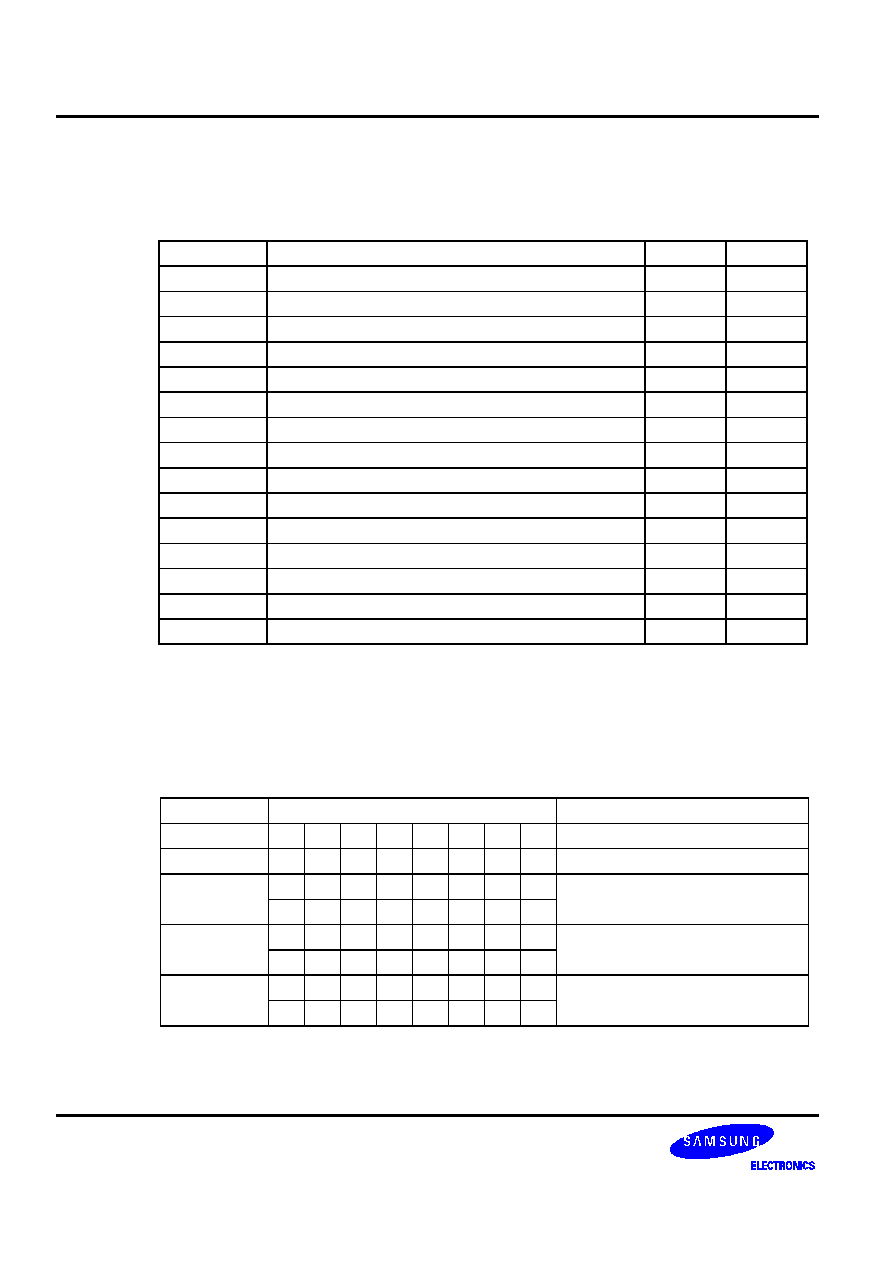
�
%
LD
dst,src
Operation: Operand
Operation
Summary
Bytes
Cycles
A,#im
Load 4-bit immediate data to A
1
1
A,@RRa
Load indirect data memory contents to A
1
1
A,DA
Load direct data memory contents to A
2
2
A,Ra
Load register contents to A
2
2
Ra,#im
Load 4-bit immediate data to register
2
2
RR,#imm
Load 8-bit immediate data to register
2
2
DA,A
Load contents of A to direct data memory
2
2
Ra,A
Load contents of A to register
2
2
EA,@HL
Load indirect data memory contents to EA
2
2
EA,DA
Load direct data memory contents to EA
2
2
EA,RRb
Load register contents to EA
2
2
@HL,A
Load contents of A to indirect data memory
1
1
DA,EA
Load contents of EA to data memory
2
2
RRb,EA
Load contents of EA to register
2
2
@HL,EA
Load contents of EA to indirect data memory
2
2
Description: The contents of the source are loaded into the destination. The source's contents are unaffected.
If an instruction such as 'LD A,#im' (LD EA,#imm) or 'LD HL,#imm' is written more than two
times in succession, only the first LD will be executed; the other similar instructions that
immediately follow the first LD will be treated like a NOP. This is called the 'redundancy effect'
(see examples below).
Operand
Binary Code
Operation Notation
A,#im
1 0 1 1 d3 d2 d1 d0
A
im
A,@RRa
1 0 0 0 1 i2 i1 i0
A
(RRa)
A,DA
1 0 0 0 1 1 0 0 A
DA
a7 a6 a5 a4 a3 a2 a1 a0
A,Ra
1 1 0 1 1 1 0 1 A
Ra
0 0 0 0 1 r2 r1 r0
Ra,#im
1 1 0 1 1 0 0 1 Ra
im
d3 d2 d1 d0 1 r2 r1 r0
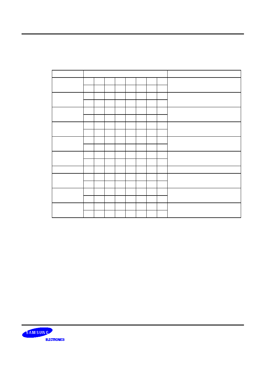
�
%
LD
(Continued)
Description:
Operand
Binary Code
Operation Notation
RR,#imm
1 0 0 0 0 r2 r1 1 RR
imm
d7 d6 d5 d4 d3 d2 d1 d0
DA,A
1 0 0 0 1 0 0 1 DA
A
a7 a6 a5 a4 a3 a2 a1 a0
Ra,A
1 1 0 1 1 1 0 1 Ra
A
0 0 0 0 0 r2 r1 r0
EA,@HL
1 1 0 1 1 1 0 0 A
(HL), E
(HL + 1)
0 0 0 0 1 0 0 0
EA,DA
1 1 0 0 1 1 1 0 A
DA, E
DA + 1
a7 a6 a5 a4 a3 a2 a1 a0
EA,RRb
1 1 0 1 1 1 0 0 EA
RRb
1 1 1 1 0 r2 r1 0
@HL,A
1 1 0 0 0 1 0 0 (HL)
A
DA,EA
1 1 0 0 1 1 0 1 DA
A, DA + 1
E
a7 a6 a5 a4 a3 a2 a1 a0
RRb,EA
1 1 0 1 1 1 0 0 RRb
EA
1 1 1 1 0 r2 r1 0
@HL,EA
1 1 0 1 1 1 0 0 (HL)
A, (HL + 1)
E
0 0 0 0 0 0 0 0
Examples:
1. RAM location 30H contains the value 4H. The RAM location values are 40H, 41H and 0AH,
3H respectively. The following instruction sequence leaves the value 40H in point pair HL,
0AH in the accumulator and in RAM location 40H, and 3H in register E.
LD HL,#30H
;
HL
30H
LD A,@HL
;
A
4H
LD HL,#40H
;
HL
40H
LD EA,@HL
;
A
0AH, E
3H
LD @HL,A
;
RAM
(40H)
0AH

�
%
LD
(Continued)
Examples:
2. If an instruction such as LD A,#im (LD EA,#imm) or LD HL,#imm is written more than two
times in succession, only the first LD is executed; the next instructions are treated as NOPs.
Here are two examples of this 'redundancy effect':
LD A,#1H
;
A
1H
LD EA,#2H
;
NOP
LD A,#3H
;
NOP
LD 23H,A
;
(23H)
1H
LD HL,#10H
;
HL
10H
LD HL,#20H
;
NOP
LD A,#3H
;
A
3H
LD EA,#35
;
NOP
LD @HL,A
;
(10H)
3H
The following table contains descriptions of special characteristics of the LD instruction when used
in different addressing modes:
Instruction
Operation Description and Guidelines
LD A,#im
Since the 'redundancy effect' occurs with instructions like LD EA,#imm, if this
instruction is used consecutively, the second and additional instructions of the
same type will be treated like NOPs.
LD A,@RRa Load the data memory contents pointed to by 8-bit RRa register pairs (HL, WX,
WL) to the A register.
LD A,DA
Load direct data memory contents to the A register.
LD A,Ra
Load 4-bit register Ra (E, L, H, X, W, Z, Y) to the A register.
LD Ra,#im
Load 4-bit immediate data into the Ra register (E, L, H, X, W, Y, Z).
LD RR,#imm Load 8-bit immediate data into the Ra register (EA, HL, WX, YZ). There is a
redundancy effect if the operation addresses the HL or EA registers.
LD DA,A
Load contents of register A to direct data memory address.
LD Ra,A
Load contents of register A to 4-bit Ra register (E, L, H, X, W, Z, Y).

�
%
LD
(Concluded)
Examples: Instruction
Operation Description and Guidelines
LD EA,@HL Load data memory contents pointed to by 8-bit register HL to the A register, and
the contents of HL+1 to the E register. The contents of register L must be an
even number. If the number is odd, the LSB of register L is recognized as a
logic zero (an even number), and it is not replaced with the true value. For
example, 'LD HL,#36H' loads immediate 36H to HL and the next instruction 'LD
EA,@HL' loads the contents of 36H to register A and the contents of 37H to
register E.
LD EA,DA
Load direct data memory contents of DA to the A register, and the next direct
data memory contents of DA + 1 to the E register. The DA value must be an
even number. If it is an odd number, the LSB of DA is recognized as a logic
zero (an even number), and it is not replaced with the true value. For example,
'LD EA,37H' loads the contents of 36H to the A register and the contents of
37H to the E register.
LD EA,RRb
Load 8-bit RRb register (HL, WX, YZ) to the EA register. H, W, and Y register
values are loaded into the E register, and the L, X, and Z values into the A
register.
LD @HL,A
Load A register contents to data memory location pointed to by the 8-bit HL
register value.
LD DA,EA
Load the A register contents to direct data memory and the E register contents
to the next direct data memory location. The DA value must be an even
number. If it is an odd number, the LSB of the DA value is recognized as logic
zero (an even number), and is not replaced with the true value.
LD RRb,EA
Load contents of EA to the 8-bit RRb register (HL, WX, YZ). The E register is
loaded into the H, W, and Y register and the A register into the L, X, and Z
register.
LD @HL,EA Load the A register to data memory location pointed to by the 8-bit HL register,
and the E register contents to the next location, HL + 1. The contents of the L
register must be an even number. If the number is odd, the LSB of the L
register is recognized as logic zero (an even number), and is not replaced with
the true value. For example, 'LD HL,#36H' loads immediate 36H to register HL;
the instruction 'LD @HL,EA' loads the contents of A into address 36H and the
contents of E into address 37H.
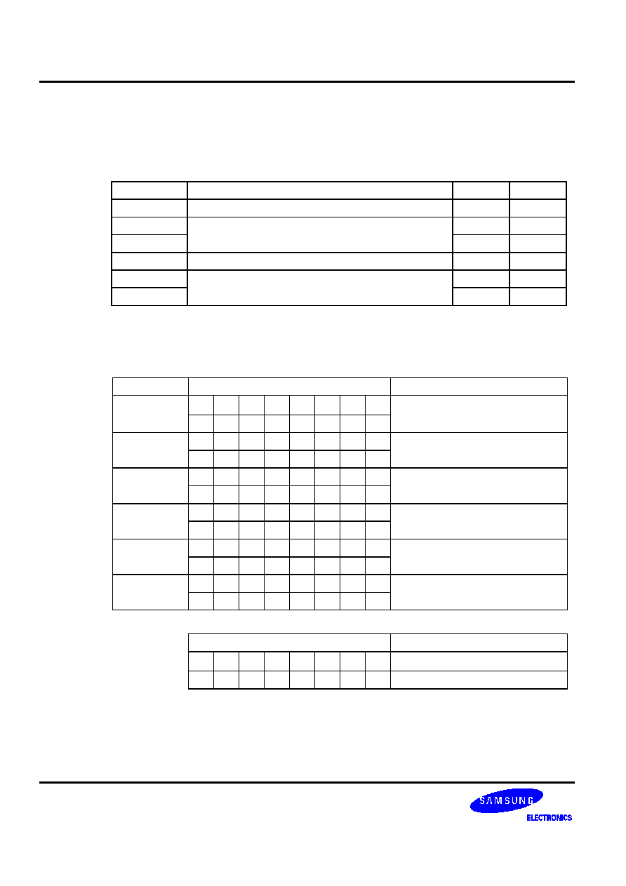
�
%
LDB
dst,src.b
LDB dst.b,src
Operation: Operand
Operation
Summary
Bytes
Cycles
mema.b,C
Load carry bit to a specified memory bit
2
2
memb.@L,C
Load carry bit to a specified indirect memory bit
2
2
@H+DA.b,C
2 2
C,mema.b
Load memory bit to a specified carry bit
2
2
C,memb.@L
Load indirect memory bit to a specified carry bit
2
2
C,@H+DA.b
2 2
Description: The Boolean variable indicated by the first or second operand is copied into the location specified
by the second or first operand. One of the operands must be the carry flag; the other may be any
directly or indirectly addressable bit. The source is unaffected.
Operand
Binary Code
Operation Notation
mema.b,C
1 1 1 1 1 1 0 0 mema.b
C
memb.@L,C 1 1 1 1 1 1 0 0 memb.7-2 + [L.3-2]. [L.1-0]
C
0 1 0 0 a5 a4 a3 a2
@H+DA.b,C 1 1 1 1 1 1 0 0 H + [DA.3-0].b
(C)
0 0 b1 b0
a3 a2 a1 a0
C,mema.b* 1 1 1 1 0 1 0 0 C
mema.b
C,memb.@L 1 1 1 1 0 1 0 0 C
memb.7-2 + [L.3-2] . [L.1-0]
0 1 0 0 a5 a4 a3 a2
C,@H+DA.b 1 1 1 1 0 1 0 0 C
[H + DA.3-0].b
0 0 b1 b0
a3 a2 a1 a0
Second Byte
Bit Addresses
mema.b
1 0 b1 b0
a3 a2 a1 a0 FB0H-FBFH
1 1 b1 b0 a3 a2 a1 a0 FF0H-FFFH

�
%
LDB
(Continued)
Examples:
1. The carry flag is set and the data value at input pin P1.0 is logic zero. The following instruction
clears the carry flag to logic zero.
LDB C,P1.0
2. The P1 address is FF1H and the L register contains the value 1H (0001B). The address
(memb.7-2) is 111100B and (L.3-2) is 00B. The resulting address is 11110000B or FF0H and
P0 is addressed. The bit value (L.1-0) is specified as 01B (bit 1).
LD L,#0001B
LDB
C,P1.@L
; P1.@L specifies P0.1 and C
P0.1
3. The H register contains the value 2H and FLAG = 20H.3. The address for H is 0010B and for
FLAG(3-0) the address is 0000B. The resulting address is 00100000B or 20H. The bit value is
3. Therefore, @H+FLAG = 20H.3.
FLAG
EQU
20H.3
LD H,#2H
LDB C,@H+FLAG
;
C
FLAG (20H.3)
4. The following instruction sequence sets the carry flag and the loads the "1" data value to the
output pin P1.0, setting it to output mode:
SCF
;
C
"1"
LDB P1.0,C
;
P1.0
"1"
5. The P1 address is FF1H and L = 01H (0001B). The address (memb.7-2) is 111100B and (L.3-
2) is 00B. The resulting address, 11110000B specifies P0. The bit value (L.1-0) is specified as
01B (bit 1). Therefore, P1.@L = P0.1.
SCF
;
C
"1"
LD L,#
0001B
LDB P1.@L,C
;
P1.@L
specifies
P0.1
;
P0.1
"1"
6. In this example, H = 2H and FLAG = 20H.3 and the address 20H is specified. Since the bit
value is 3, @H+FLAG = 20H.3:
FLAG
EQU
20H.3
RCF
;
C
"0"
LD H,#2H
LDB @H+FLAG,C
;
FLAG(20H.3)
"0"
, #
9
6
:
�
�
%�%'"'
LDC
dst,src
Operation: Operand
Operation
Summary
Bytes
Cycles
EA,@WX
Load code byte from WX to EA
1
3
EA,@EA
Load code byte from EA to EA
1
3
Description: This instruction is used to load a byte from program memory into an extended accumulator. The
address of the byte fetched is the six highest bit values in the program counter and the contents of
an 8-bit working register (either WX or EA). The contents of the source are unaffected.
Operand
Binary Code
Operation Notation
EA,@WX
1 1 0 0 1 1 0 0 EA
[PC14-8 + (WX)]
EA,@EA
1 1 0 0 1 0 0 0 EA
[PC14-8 + (EA)]
Examples:
1. The following instructions will load one of four values defined by the define byte (DB) directive
to the extended accumulator:
LD
EA,#00H
CALL DISPLAY
JPS
MAIN
ORG 0500H
DB
66H
DB
77H
DB
88H
DB
99H
DISPLAY
LDC EA,@EA
;
EA
address 0500H = 66H
RET
If the instruction 'LD EA,#01H' is executed in place of 'LD EA,#00H', The content of 0501H
(77H) is loaded to the EA register. If 'LD EA,#02H' is executed, the content of address 0502H
(88H) is loaded to EA.

�
�
%�%'"'
LDC
(Continued)
Examples:
2. The following instructions will load one of four values defined by the define byte (DB) directive
to the extended accumulator:
ORG 0500H
DB
66H
DB
77H
DB
88H
DB
99H
DISPLAY
LD
WX,#00H
LDC EA,@WX
;
EA
address 0500H = 66H
RET
If the instruction 'LD WX,#01H' is executed in place of 'LD WX,#00H', then
EA
address 0501H = 77H.
If the instruction 'LD WX,#02H' is executed in place of 'LD WX,#00H', then
EA
address 0502H = 88H.
3. Normally, the LDC EA, @EA and the LDC EA, @WX instructions reference the table data
on the page on which the instruction is located. If, however, the instruction is located at
address xxFFH, it will reference table data on the next page. In this example, the upper 4 bits
of the address at location 0200H is loaded into register E and the lower 4 bits into register A:
ORG 01FDH
01FDH
LD
WX,#00H
01FFH
LDC EA,@WX
;
E
upper 4 bits of 0200H address
; A
lower 4 bits of 0200H address
4. Here is another example of page referencing with the LDC instruction:
ORG 0100H
DB
67H
SMB 0
LD
HL,#30H
;
Even
number
LD
WX,#00H
LDC EA,@WX
;
E
upper 4 bits of 0100H address
; A
lower 4 bits of 0100H address
LD
@HL,EA
;
RAM
(30H)
7, RAM (31H)
6
�
%'2%!"'+!'2'
LDD
dst
Operation: Operand
Operation
Summary
Bytes
Cycles
A,@HL
Load indirect data memory contents to A; decrement
register L contents and skip on borrow
1
2 + S
Description: The contents of a data memory location are loaded into the accumulator, and the contents of the
register L are decreased by one. If a "borrow" occurs (e.g., if the resulting value in register L is
0FH), the next instruction is skipped. The contents of data memory and the carry flag value are not
affected.
Operand
Binary Code
Operation Notation
A,@HL
1 0 0 0 1 0 1 1 A
(HL), then L
L-1;
skip if L = 0FH
Example:
In this example, assume that register pair HL contains 20H and internal RAM location 20H
contains the value 0FH:
LD
HL,#20H
LDD A,@HL
;
A
(HL) and L
L-1
JPS XXX
;
Skip
JPS YYY
;
H
2H and L
0FH
The instruction 'JPS XXX' is skipped since a "borrow" occurred after the 'LDD A,@HL' and
instruction 'JPS YYY' is executed.
�
%'2%!"+!'2'
LDI
dst,src
Operation: Operand
Operation
Summary
Bytes
Cycles
A,@HL
Load indirect data memory to A; increment register L
contents and skip on overflow
1
2 + S
Description: The contents of a data memory location are loaded into the accumulator, and the contents of the
register L are incremented by one. If an overflow occurs (e.g., if the resulting value in register L is
0H), the next instruction is skipped. The contents of data memory and the carry flag value are
unaffected.
Operand
Binary Code
Operation Notation
A,@HL
1 0 0 0 1 0 1 0 A
(HL), then L
L+1;
skip if L = 0H
Example:
Assume that register pair HL contains the address 2FH and internal RAM location 2FH contains
the value 0FH:
LD
HL,#2FH
LDI
A,@HL
; A
(HL) and L
L+1
JPS XXX
;
Skip
JPS YYY
;
H
2H and L
0H
The instruction 'JPS XXX' is skipped since an overflow occurred after the 'LDI A,@HL' and the
instruction 'JPS YYY' is executed.

�
5-2$
JP
dst
Operation: Operand
Operation
Summary
Bytes
Cycles
ADR15
Jump to direct address (15 bits)
3
3
Description: JP causes an unconditional branch to the indicated address by replacing the contents of the
program counter with the address specified in the destination operand. The destination can be
anywhere in the 32-Kbyte program memory address space.
The LJP instruction can be used in the all range (0000H-7FFFH) while the JP instruction can be
used in the only range (0000H-3FFFH).
Operand
Binary Code
Operation Notation
ADR15
1 1 0 1 1 0 0 0
PC14-0
ADR15
0 a14 a13 a12 a11 a10 a9 a8
a7 a6 a5 a4 a3 a2 a1 a0
Example:
The label 'SYSCON' is assigned to the instruction at program location 5FFFH. The instruction
LJP
SYSCON
at location 0123H will load the program counter with the value 5FFFH.

�
%$'!%
NOP
Operation: Operand
Operation
Summary
Bytes
Cycles
�
No
operation
1
1
Description: No operation is performed by a NOP instruction. It is typically used for timing delays.
One NOP causes a 1-cycle delay: with a 1 �s cycle time, five NOPs would therefore cause a 5 �s
delay. Program execution continues with the instruction immediately following the NOP. Only the
PC is affected. At least three NOP instructions should follow a STOP or IDLE instruction.
Operand
Binary Code
Operation Notation
�
1 0 1 0 0 0 0 0 No
operation
Example:
Three NOP instructions follow the STOP instruction to provide a short interval for clock
stabilization before power-down mode is initiated:
STOP
NOP
NOP
NOP
�
%*+)
OR
dst,src
Operation: Operand
Operation
Summary
Bytes
Cycles
A, #im
Logical-OR immediate data to A
2
2
A, @HL
Logical-OR indirect data memory contents to A
1
1
EA,RR
Logical-OR double register to EA
2
2
RRb,EA
Logical-OR EA to double register
2
2
Description: The source operand is logically ORed with the destination operand. The result is stored in the
destination. The contents of the source are unaffected.
Operand
Binary Code
Operation Notation
A,
#im
1 1 0 1 1 1 0 1 A
A OR im
0 0 1 0 d3 d2 d1 d0
A,
@HL
0 0 1 1 1 0 1 0 A
A OR (HL)
EA,RR
1 1 0 1 1 1 0 0 EA
EA OR RR
0 0 1 0 1 r2 r1 0
RRb,EA
1 1 0 1 1 1 0 0 RRb
RRb OR EA
0 0 1 0 0 r2 r1 0
Example:
If the accumulator contains the value 0C3H (11000011B) and register pair HL the value 55H
(01010101B), the instruction
OR
EA,@HL
leaves the value 0D7H (11010111B) in the accumulator .
�
%$(!%2+#
POP
dst
Operation: Operand
Operation
Summary
Bytes
Cycles
RR
Pop to register pair from stack
1
1
SB
Pop SMB and SRB values from stack
2
2
Description: The contents of the RAM location addressed by the stack pointer is read, and the SP is
incremented by two. The value read is then transferred to the variable indicated by the destination
operand.
Operand
Binary Code
Operation Notation
RR
0 0 1 0 1 r2 r1 0 RR
&
(SP), RR
;
(SP+1)
SP
SP+2
SB
1 1 0 1 1 1 0 1 (SRB)
(SP), SMB
(SP+1),
SP
SP+2
0 1 1 0 0 1 1 0
Example:
The SP value is equal to 0EDH, and RAM locations 0EFH through 0EDH contain the values 2H,
3H, and 4H, respectively. The instruction
POP HL
leaves the stack pointer set to 0EFH and the data pointer pair HL set to 34H.
�
-, %+#
PUSH
src
Operation: Operand
Operation
Summary
Bytes
Cycles
RR
Push register pair onto stack
1
1
SB
Push SMB and SRB values onto stack
2
2
Description: The SP is then decreased by two and the contents of the source operand are copied into the RAM
location addressed by the stack pointer, thereby adding a new element to the top of the stack.
Operand
Binary Code
Operation Notation
RR
0 0 1 0 1 r2 r1 1 (SP-1)
RR
;
, (SP-2)
RR
&
SP
SP-2
SB
1 1 0 1 1 1 0 1 (SP-1)
SMB, (SP-2)
SRB;
(SP)
SP-2
0 1 1 0 0 1 1 1
Example:
As an interrupt service routine begins, the stack pointer contains the value 0FAH and the data
pointer register pair HL contains the value 20H. The instruction
PUSH HL
leaves the stack pointer set to 0F8H and stores the values 2H and 0H in RAM locations 0F9H and
0F8H, respectively.
�
�
','�!!"
)*
RCF
Operation: Operand
Operation
Summary
Bytes
Cycles
�
Reset carry flag to logic zero
1
1
Description: The carry flag is cleared to logic zero, regardless of its previous value.
Operand
Binary Code
Operation Notation
�
1 1 1 0 0 1 1 0 C
0
Example:
Assuming the carry flag is set to logic one, the instruction
RCF
resets (clears) the carry flag to logic zero.
�
'('!'+',!-+%
REF
dst
Operation: Operand
Operation
Summary
Bytes
Cycles
memc Reference
code
1 3
, 34
5<%&&
Description: The REF instruction is used to rewrite into 1-byte form, arbitrary 2-byte or 3-byte instructions (or
two 1-byte instructions) stored in the REF instruction reference area in program memory. REF
reduces the number of program memory accesses for a program.
Operand
Binary Code
Operation Notation
memc
t7 t6 t5 t4 t3 t2 t1 t0 PC13-0
memc.7-4,
memc.3-0 < 1
TJP and TCALL are 2-byte pseudo-instructions that are used only to specify the reference area:
1. When the reference area is specified by the TJP instruction,
memc.7-6 = 00
PC13-0
memc.5-0 + (memc + 1).7-0
2. When the reference area is specified by the TCALL instruction,
memc.7-6 = 01
[(SP-1)
(SP-2)]
EMB, ERB
[(SP-3)
(SP-4)]
PC7-0
[(SP-5)
(SP-6)]
PC13-8
SP
SP-6
PC13-0
memc.5-0 + (memc + 1).7-0
When the reference area is specified by any other instruction, the 'memc' and 'memc + 1'
instructions are executed.
Instructions referenced by REF occupy 2 bytes of memory space (for two 1-byte instructions or
one 2-byte instruction) and must be written as an even number from 0020H to 007FH in ROM. In
addition, the destination address of the TJP and TCALL instructions must be located with the
3FFFH address. TJP and TCALL are reference instructions for JP/JPS and CALL/CALLS.
If the instruction following a REF is subject to the 'redundancy effect', the redundant instruction is
skipped. If, however, the REF follows a redundant instruction, it is executed.
On the other hand, the binary code of a REF instruction is 1 byte. The upper 4 bits become the
higher address bits of the referenced instruction, and the lower 4 bits of the referenced instruction
becomes the lower address, producing a total of 8 bits or 1 byte (see Example 3 below).
, 2*
=
-./$
34

�
'('!'+',!-+%
REF
(Continued)
Examples:
1. Instructions can be executed efficiently using REF, as shown in the following example:
ORG 0020H
AAA LD
HL,#00H
BBB LD
EA,#FFH
CCC TCALL SUB1
DDD TJP
SUB2
ORG
0080H
REF AAA ;
LD HL,#00H
REF BBB ;
LD EA,#FFH
REF CCC ;
CALL
SUB1
REF DDD ;
JP SUB2
2. The following example shows how the REF instruction is executed in relation to LD
instructions that have a 'redundancy effect':
ORG 0020H
AAA LD
EA,#40H
ORG 0100H
LD
EA,#30H
REF AAA ;
Not
skipped
REF AAA
LD
EA,#50H
;
Skipped
SRB 2

�
'('!'+',!-+%
REF
(Concluded)
Examples:
3. In this example the binary code of 'REF A1' at locations 20H-21H is 20H, for 'REF A2' at
locations 22H-23H, it is 21H, and for 'REF A3' at 24H-25H, the binary code is 22H :
Opcode Symbol Instruction
ORG
0020H
83 00
A1
LD
HL,#00H
83 03
A2
LD
HL,#03H
83 05
A3
LD
HL,#05H
83 10
A4
LD
HL,#10H
83 26
A5
LD
HL,#26H
83 08
A6
LD
HL,#08H
83 0F
A7
LD
HL,#0FH
83 F0
A8
LD
HL,#0F0H
83 67
A9
LD
HL,#067H
41 0B A10
TCALL SUB1
01 0D A11
TJP
SUB2
ORG 0100H
20 REF
A1 ;
LD HL,#00H
21 REF
A2 ;
LD HL,#03H
22 REF
A3 ;
LD HL,#05H
23 REF
A4 ;
LD HL,#10H
24 REF
A5 ;
LD HL,#26H
25 REF
A6 ;
LD HL,#08H
26 REF
A7 ;
LD HL,#0FH
27 REF
A8 ;
LD HL,#0F0H
30 REF
A9 ;
LD HL,#067H
31 REF
A10 ;
CALL
SUB1
32 REF
A11 ;
JP SUB2
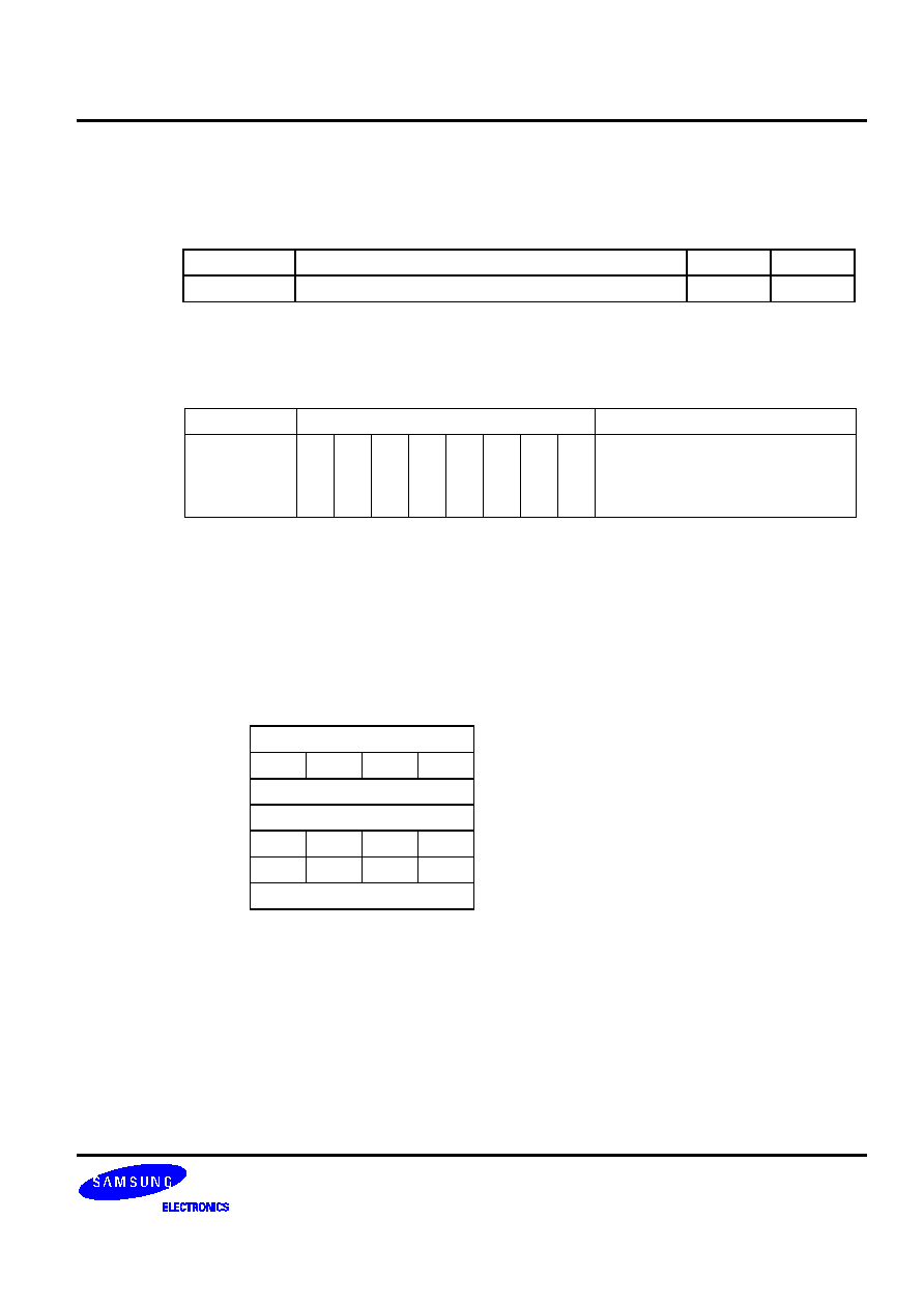
�
'-!(!%2-4!%-'
RET
Operation: Operand
Operation
Summary
Bytes
Cycles
�
Return from subroutine
1
3
Description: RET pops the PC values successively from the stack, incrementing the stack pointer by six.
Program execution continues from the resulting address, generally the instruction immediately
following a CALL, LCALL or CALLS.
Operand
Binary Code
Operation Notation
�
1 1 0 0 0 1 0 1 PC14-8
(SP+1) (SP)
PC7-0
(SP+3) (SP+2)
EMB,ERB
(SP+5) (SP+4)
SP
SP+6
Example:
The stack pointer contains the value 0FAH. RAM locations 0FAH, 0FBH, 0FCH, and 0FDH
contain 1H, 0H, 5H, and 2H, respectively. The instruction
RET
leaves the stack pointer with the new value of 00H and program execution continues from location
0125H.
During a return from subroutine, PC values are popped from stack locations as follows:
SP
(0FAH)
PC11 - PC8
SP + 1
(0FBH)
0
PC14 PC13 PC12
SP + 2
(0FCH)
PC3 - PC0
SP + 3
(0FDH)
PC7 - PC4
SP + 4
(0FEH)
0
0
EMB
ERB
SP
+
5 (0FFH)
0 0 0 0
SP + 6
(000H)
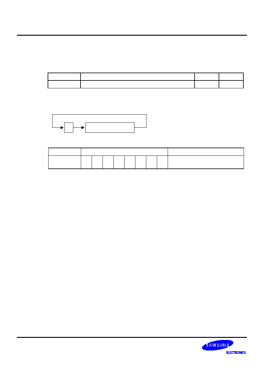
�
�
%'++-2-)%!* !%-* �!!"
RRC
A
Operation: Operand
Operation
Summary
Bytes
Cycles
A
Rotate right through carry bit
1
1
Description: The four bits in the accumulator and the carry flag are together rotated one bit to the right. Bit 0
moves into the carry flag and the original carry value moves into the bit 3 accumulator position.
%
+
.
Operand
Binary Code
Operation Notation
A
1 0 0 0 1 0 0 0 C
A.0, A3
C
A.n-1
A.n (n = 1, 2, 3)
Example:
The accumulator contains the value 5H (0101B) and the carry flag is cleared to logic zero. The
instruction
RRC A
leaves the accumulator with the value 2H (0010B) and the carry flag set to logic one.
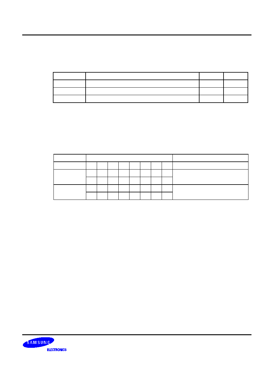
�
�
-4!+ �!!"
SBC
dst,src
Operation: Operand
Operation
Summary
Bytes
Cycles
A,@HL
Subtract indirect data memory from A with carry
1
1
EA,RR
Subtract register pair (RR) from EA with carry
2
2
RRb,EA
Subtract EA from register pair (RRb) with carry
2
2
Description: SBC subtracts the source and carry flag value from the destination operand, leaving the result in
the destination. SBC sets the carry flag if a borrow is needed for the most significant bit; otherwise
it clears the carry flag. The contents of the source are unaffected.
If the carry flag was set before the SBC instruction was executed, a borrow was needed for the
previous step in multiple precision subtraction. In this case, the carry bit is subtracted from the
destination along with the source operand.
Operand
Binary Code
Operation Notation
A,@HL
0 0 1 1 1 1 0 0 C,A
A - (HL) - C
EA,RR
1 1 0 1 1 1 0 0 C, EA
EA -RR - C
1 1 0 0 1 r2 r1 0
RRb,EA
1 1 0 1 1 1 0 0 C,RRb
RRb - EA - C
1 1 0 0 0 r2 r1 0
Examples:
1. The extended accumulator contains the value 0C3H, register pair HL the value 0AAH, and
the carry flag is set to "1":
SCF
;
C
"1"
SBC EA,HL
;
EA
0C3H - 0AAH - 1H, C
"0"
JPS
XXX
; Jump to XXX; no skip after SBC
2. If the extended accumulator contains the value 0C3H, register pair HL the value 0AAH, and
the carry flag is cleared to "0":
RCF
;
C
"0"
SBC EA,HL
;
EA
0C3H - 0AAH - 0H = 19H, C
"0"
JPS
XXX
; Jump to XXX; no skip after SBC

�
�
-4!+ �!!"
SBC
(Continued)
Examples:
3. If SBC A,@HL is followed by an ADS A,#im, the SBC skips on 'no borrow' to the instruction
immediately after the ADS. An 'ADS A,#im' instruction immediately after the 'SBC A,@HL'
instruction does not skip even if an overflow occurs. This function is useful for decimal
adjustment
operations.
a. 8 - 6 decimal addition (the contents of the address specified by the HL register is 6H):
RCF
;
C
"0"
LD A,#8H
;
A
8H
SBC A,@HL
;
A
8H - 6H - C(0) = 2H, C
"0"
ADS
A,#0AH
; Skip this instruction because no borrow after SBC result
JPS XXX
b. 3 - 4 decimal addition (the contents of the address specified by the HL register is 4H):
RCF
;
C
"0"
LD A,#3H
;
A
3H
SBC A,@HL
;
A
3H - 4H - C(0) = 0FH, C
"1"
ADS
A,#0AH
; No skip. A
0FH + 0AH = 9H
; (The skip function of 'ADS A,#im' is inhibited after a
; 'SBC A,@HL' instruction even if an overflow occurs.)
JPS XXX
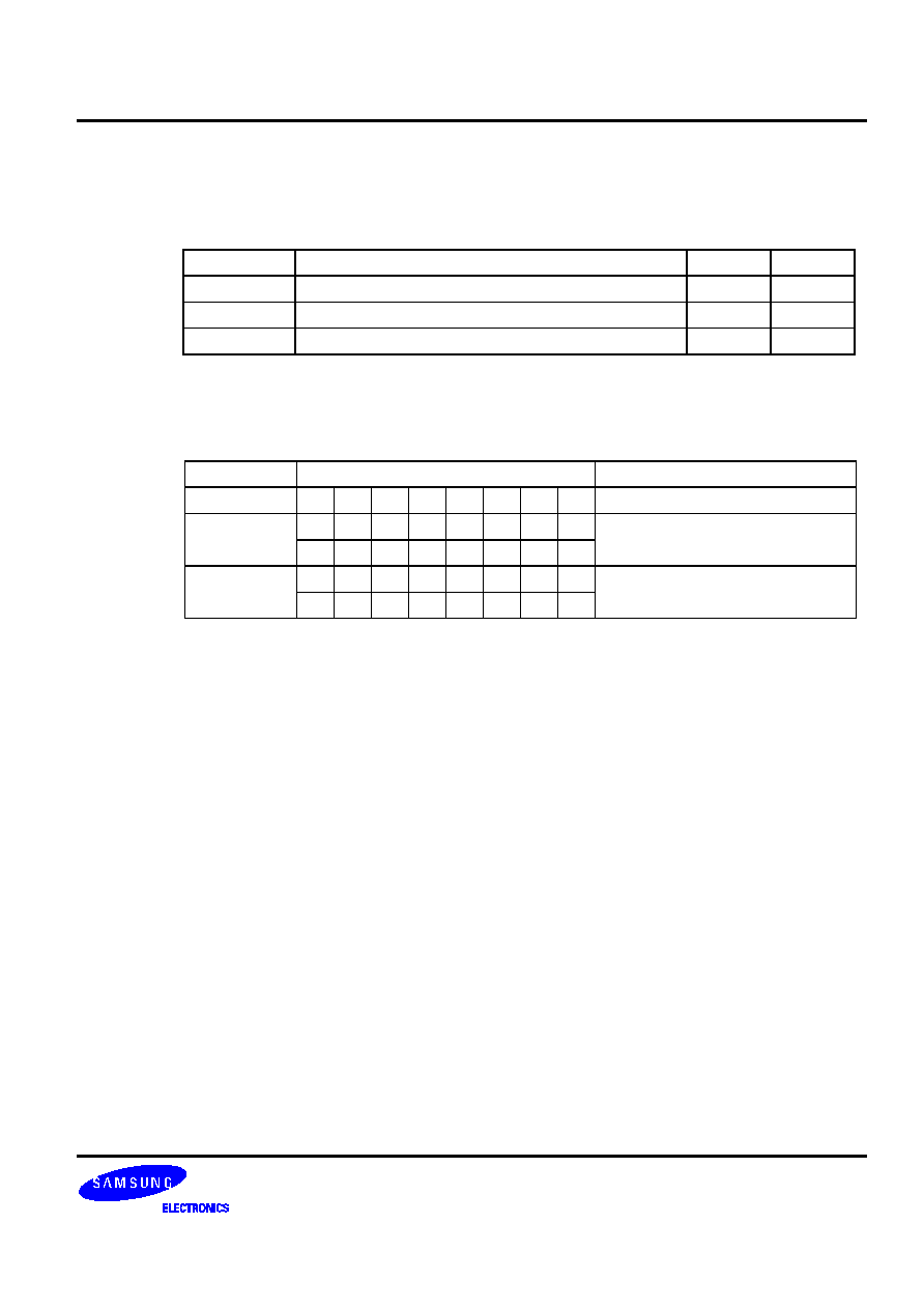
�
-4!+
SBS
dst,src
Operation: Operand
Operation
Summary
Bytes
Cycles
A,@HL
Subtract indirect data memory from A; skip on borrow
1
1 + S
EA,RR
Subtract register pair (RR) from EA; skip on borrow
2
2 + S
RRb,EA
Subtract EA from register pair (RRb); skip on borrow
2
2 + S
Description: The source operand is subtracted from the destination operand and the result is stored in the
destination. The contents of the source are unaffected. A skip is executed if a borrow occurs. The
value of the carry flag is not affected.
Operand
Binary Code
Operation Notation
A,@HL
0 0 1 1 1 1 0 1 A
A - (HL); skip on borrow
EA,RR
1 1 0 1 1 1 0 0 EA
EA - RR; skip on borrow
1 0 1 1 1 r2 r1 0
RRb,EA
1 1 0 1 1 1 0 0 RRb
RRb - EA; skip on borrow
1 0 1 1 0 r2 r1 0
Examples:
1. The accumulator contains the value 0C3H, register pair HL contains the value 0C7H, and the
carry flag is cleared to logic zero:
RCF
;
C
"0"
SBS EA,HL
;
EA
0C3H - 0C7H
; SBS instruction skips on borrow,
; but carry flag value is not affected
JPS
XXX
; Skip because a borrow occurred
JPS
YYY
; Jump to YYY is executed
2. The accumulator contains the value 0AFH, register pair HL contains the value 0AAH, and the
carry flag is set to logic one:
SCF
;
C
"1"
SBS EA,HL
;
EA
0AFH - 0AAH
JPS XXX
;
Jump
to
XXX
; JPS was not skipped since no "borrow" occurred after
;
SBS
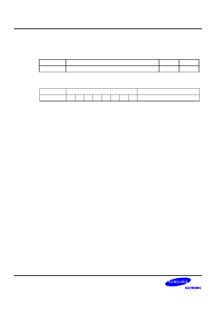
�
�
'�!!"
)*
SCF
Operation: Operand
Operation
Summary
Bytes
Cycles
�
Set carry flag to logic one
1
1
Description: The SCF instruction sets the carry flag to logic one, regardless of its previous value.
Operand
Binary Code
Operation Notation
�
1 1 1 0 0 1 1 1 C
1
Example:
If the carry flag is cleared to logic zero, the instruction
SCF
sets the carry flag to logic one.

�
')'+'2%!"#
SMB
n
Operation: Operand
Operation
Summary
Bytes
Cycles
n
Select memory bank
2
2
Description: The SMB instruction sets the upper four bits of a 12-bit data memory address to select a specific
memory bank. The constants 0, n, and 15 are usually used as the SMB operand to select the
corresponding memory bank. All references to data memory addresses fall within the following
address ranges:
Please note that since data memory spaces differ for various devices in the SAM4 product family,
the 'n' value of the SMB instruction will also vary.
Addresses
Register
Areas
Bank
SMB
000H-01FH
Working
registers
0 0
020H-0FFH
Stack and general-purpose registers
n00H-nFFH
General-purpose registers
n
(n = 1-14)
n
(n = 1-14)
F80H-FFFH
I/O-mapped hardware registers
15
15
The enable memory bank (EMB) flag must always be set to "1" in order for the SMB instruction to
execute successfully for memory banks 0-15.
Format
Binary Code
Operation Notation
n
1 1 0 1 1 1 0 1 SMB
n (n = 0-15)
0 1 0 0 d3 d2 d1 d0
Example:
If the EMB flag is set, the instruction
SMB 0
selects the data memory address range for bank 0 (000H-0FFH) as the working memory bank.
,
)
*
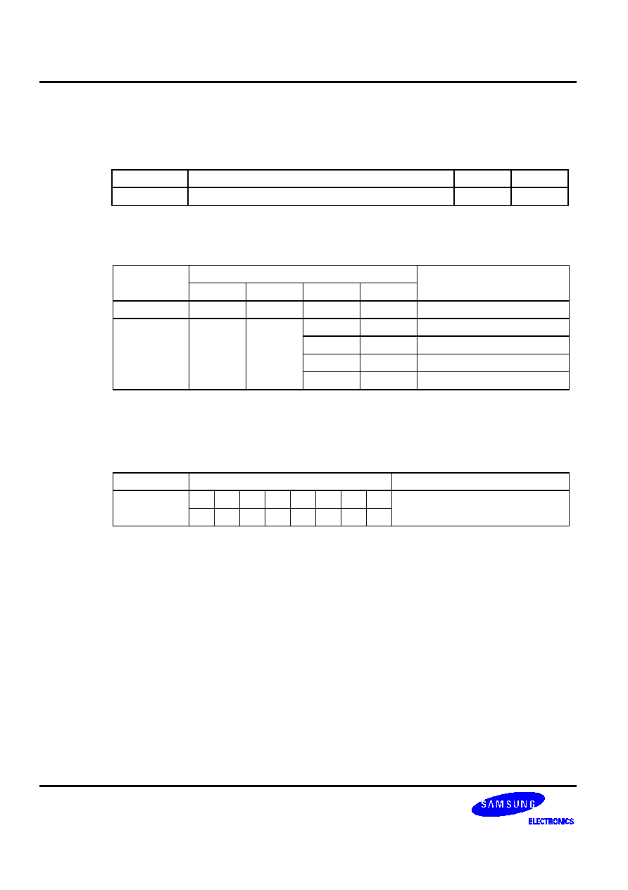
�
')'+'*,'!#
SRB
n
Operation: Operand
Operation
Summary
Bytes
Cycles
n
Select register bank
2
2
Description: The SRB instruction selects one of four register banks in the working register memory area. The
constant value used with SRB is 0, 1, 2, or 3. The following table shows the effect of SRB settings:
ERB Setting
SRB Settings
Selected Register Bank
3 2 1 0
0
0
0
x
x
Always set to bank 0
0
0 Bank
0
1 0 0 0 1
Bank
1
1
0 Bank
2
1
1 Bank
3
, >9>1
The enable register bank flag (ERB) must always be set for the SRB instruction to execute
successfully for register banks 0, 1, 2, and 3. In addition, if the ERB value is logic zero, register
bank 0 is always selected, regardless of the SRB value.
Operand
Binary Code
Operation Notation
n
1 1 0 1 1 1 0 1 SRB
n (n = 0, 1, 2, 3)
0 1 0 1 0 0 d1 d0
Example:
If the ERB flag is set, the instruction
SRB 3
selects register bank 3 (018H-01FH) as the working memory register bank.
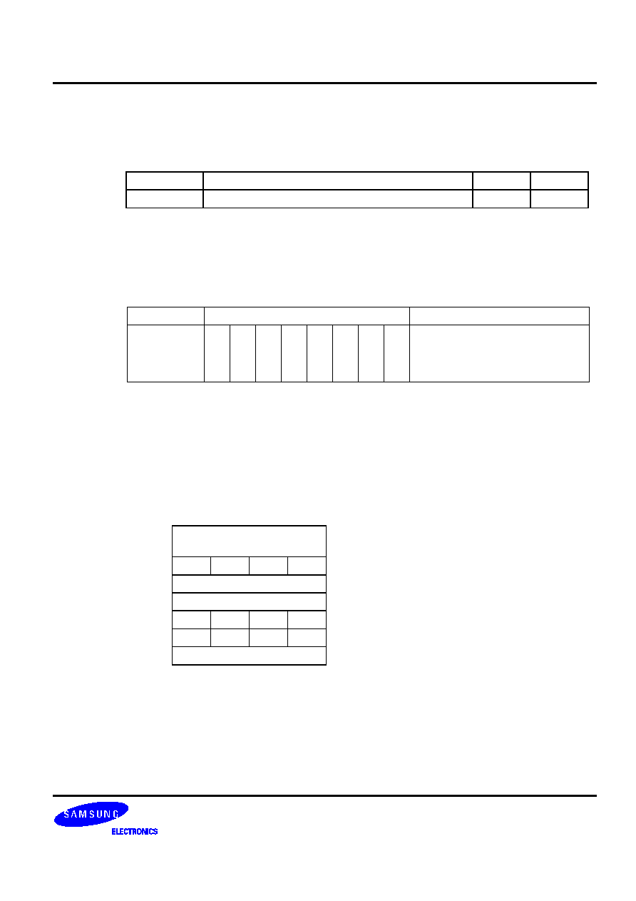
�
'-!(!%2-4!%-'#$
SRET
Operation: Operand
Operation
Summary
Bytes
Cycles
�
Return from subroutine and skip
1
3 + S
Description: SRET is normally used to return to the previously executing procedure at the end of a subroutine
that was initiated by a CALL, LCALL or CALLS instruction. SRET skips the resulting address,
which is generally the instruction immediately after the point at which the subroutine was called.
Then, program execution continues from the resulting address and the contents of the location
addressed by the stack pointer are popped into the program counter.
Operand
Binary Code
Operation Notation
�
1 1 1 0 0 1 0 1 PC14-8
(SP+1) (SP)
PC7-0
(SP+3) (SP+2)
EMB,ERB
(SP+5) (SP+4)
SP
SP+6
Example:
If the stack pointer contains the value 0FAH and RAM locations 0FAH, 0FBH, 0FCH, and 0FDH
contain the values 1H, 0H, 5H, and 2H, respectively, the instruction
SRET
leaves the stack pointer with the value 00H and the program returns to continue execution at
location 0125H, then skips unconditionally.
During a return from subroutine, data is popped from the stack to the PC as follows:
SP
(0FAH)
PC11 - PC8
SP + 1
(0FBH)
0
PC14 PC13 PC12
SP + 2
(0FCH)
PC3 - PC0
SP + 3
(0FDH)
PC7 - PC4
SP + 4
(0FEH)
0
0
EMB
ERB
SP
+
5 (0FFH)
0 0 0 0
SP + 6
(000H)

�
%$$'!%
STOP
Operation: Operand
Operation
Summary
Bytes
Cycles
�
Engage CPU stop mode
2
2
Description: The STOP instruction stops the system clock by setting bit 3 of the power control register (PCON)
to logic one. When STOP executes, all system operations are halted with the exception of some
peripheral hardware with special power-down mode operating conditions.
In application programs, a STOP instruction must be immediately followed by at least three NOP
instructions. This ensures an adequate time interval for the clock to stabilize before the next
instruction is executed. If three or more NOP instructions are not used after STOP instruction,
leakage current could be flown because of the floating state in the internal bus.
Operand
Binary Code
Operation Notation
�
1 1 1 1 1 1 1 1 PCON.3
1
1 0 1 1 0 0 1 1
Example:
Given that bit 3 of the PCON register is cleared to logic zero, and all systems are operational, the
instruction sequence
STOP
NOP
NOP
NOP
sets bit 3 of the PCON register to logic one, stopping all controller operations (with the exception
of some peripheral hardware). The three NOP instructions provide the necessary timing delay for
clock stabilization before the next instruction in the program sequence is executed.

�
%66'+%!!',,
VENTn
dst
Operation: Operand
Operation
Summary
Bytes
Cycles
EMB
(0,1)
ERB (0,1)
ADR
Load enable memory bank flag (EMB) and the enable
register bank flag (ERB) and program counter to
vector address, then branch to the corresponding
location.
2 2
Description: The VENT instruction loads the contents of the enable memory bank flag (EMB) and enable
register bank flag (ERB) into the respective vector addresses. It then points the interrupt service
routine to the corresponding branching locations. The program counter is loaded automatically
with the respective vector addresses which indicate the starting address of the respective vector
interrupt service routines.
The EMB and ERB flags should be modified using VENT before the vector interrupts are
acknowledged. Then, when an interrupt is generated, the EMB and ERB values of the previous
routine are automatically pushed onto the stack and then popped back when the routine is
completed.
After the return from interrupt (IRET) you do not need to set the EMB and ERB values again.
Instead, use BITR and BITS to clear these values in your program routine.
The starting addresses for vector interrupts and reset operations are pointed to by the VENTn
instruction. These starting addresses must be located in ROM ranges 0000H-3FFFH. Generally,
the VENTn instructions are coded starting at location 0000H.
The format for VENT instructions is as follows:
VENTn
d1,d2,ADDR
EMB
d1 ("0" or "1")
ERB
d2 ("0" or "1")
PC
ADDR (address to branch
n = device-specific module address code (n = 0-n)
Operand
Binary Code
Operation Notation
EMB
(0,1)
ERB (0,1)
ADR
E
M
B
E
R
B
a13 a12 a11 a10 a9 a8 ROM (2 x n) 7-6
EMB, ERB
ROM (2 x n) 5-4
PC13-12
ROM (2 x n) 3-0
PC11-8
ROM (2 x n + 1) 7-0
PC7-0
(n = 0, 1, 2, 3, 4, 5, 6, 7)
a7 a6 a5 a4 a3 a2 a1 a0

�
%66'+%!!',,
VENTn
(Continued)
Example:
The instruction sequence
ORG 0000H
VENT0 1,0,RESET
VENT1 0,1,INTA
VENT2 0,1,INTB
VENT3 0,1,INTC
VENT4 0,1,INTD
VENT6 0,1,INTE
VENT7 0,1,INTF
causes the program sequence to branch to the RESET routine labeled 'RESET', setting EMB to
"1" and ERB to "0" when
is activated. When a basic timer interrupt is generated, VENT1
causes the program to branch to the basic timer's interrupt service routine, INTA, and to set the
EMB value to "0" and the ERB value to "1". VENT2 then branches to INTB, VENT3 to INTC, and
so on, setting the appropriate EMB and ERB values.
, ?3@
9
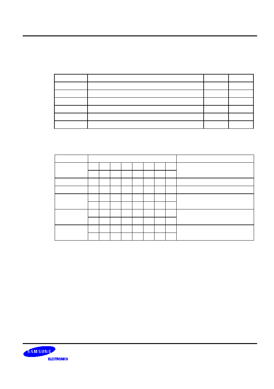
�
�
/+ *'%! 44)'%!"'
XCH
dst,src
Operation: Operand
Operation
Summary
Bytes
Cycles
A,DA
Exchange A and data memory contents
2
2
A,Ra
Exchange A and register (Ra) contents
1
1
A,@RRa
Exchange A and indirect data memory
1
1
EA,DA
Exchange EA and direct data memory contents
2
2
EA,RRb
Exchange EA and register pair (RRb) contents
2
2
EA,@HL
Exchange EA and indirect data memory contents
2
2
Description: The instruction XCH loads the accumulator with the contents of the indicated destination variable
and writes the original contents of the accumulator to the source.
Operand
Binary Code
Operation Notation
A,DA
0 1 1 1 1 0 0 1 A
DA
a7 a6 a5 a4 a3 a2 a1 a0
A,Ra
0 1 1 0 1 r2 r1 r0
A
Ra
A,@RRa
0 1 1 1 1 i2 i1 i0
A
(RRa)
EA,DA
1 1 0 0 1 1 1 1 A
DA,E
DA + 1
a7 a6 a5 a4 a3 a2 a1 a0
EA,RRb
1 1 0 1 1 1 0 0 EA
RRb
1 1 1 0 0 r2 r1 0
EA,@HL
1 1 0 1 1 1 0 0 A
(HL), E
(HL + 1)
0 0 0 0 0 0 0 1
Example:
Double register HL contains the address 20H. The accumulator contains the value 3FH
(00111111B) and internal RAM location 20H the value 75H (01110101B). The instruction
XCH EA,@HL
leaves RAM location 20H with the value 3FH (00111111B) and the extended accumulator with the
value 75H (01110101B).

�
�
/+ *''+!'2'
XCHD
dst,src
Operation: Operand
Operation
Summary
Bytes
Cycles
A,@HL
Exchange A and data memory contents; decrement
contents of register L and skip on borrow
1
2 + S
Description: The instruction XCHD exchanges the contents of the accumulator with the RAM location
addressed by register pair HL and then decrements the contents of register L. If the content of
register L is 0FH, the next instruction is skipped. The value of the carry flag is unaffected.
Operand
Binary Code
Operation Notation
A,@HL
0 1 1 1 1 0 1 1 A
(HL), then L
L-1;
skip if L = 0FH
Example:
Register pair HL contains the address 20H and internal RAM location 20H contains the value 0FH:
LD
HL,#20H
LD
A,#0H
XCHD
A,@HL ;
A
0FH and L
L - 1, (HL)
"0"
JPS
XXX
; Skipped since a borrow occurred
JPS
YYY ;
H
2H, L
0FH
YYY XCHD A,@HL
;
(2FH)
0FH, A
(2FH), L
L - 1 = 0EH
The 'JPS YYY' instruction is executed since a skip occurs after the XCHD instruction.

�
�
/+ *'+!'2'
XCHI
dst,src
Operation: Operand
Operation
Summary
Bytes
Cycles
A,@HL
Exchange A and data memory contents; increment
contents of register L and skip on overflow
1
2 + S
Description: The instruction XCHI exchanges the contents of the accumulator with the RAM location addressed
by register pair HL and then increments the contents of register L. If the content of register L is 0H,
a skip is executed. The value of the carry flag is unaffected.
Operand
Binary Code
Operation Notation
A,@HL
0 1 1 1 1 0 1 0 A
(HL), then L
L+1;
skip if L = 0H
Example:
Register pair HL contains the address 2FH and internal RAM location 2FH contains 0FH:
LD
HL,#2FH
LD
A,#0H
XCHI
A,@HL ;
A
0FH and L
L + 1 = 0, (HL)
"0"
JPS
XXX
; Skipped since an overflow occurred
JPS
YYY ;
H
2H, L
0H
YYY XCHI A,@HL
;
(20H)
0FH, A
(20H), L
L + 1 = 1H
The 'JPS YYY' instruction is executed since a skip occurs after the XCHI instruction.

�
%*+)/+)-,&'
XOR
dst,src
Operation: Operand
Operation
Summary
Bytes
Cycles
A,#im
Exclusive-OR immediate data to A
2
2
A,@HL
Exclusive-OR indirect data memory to A
1
1
EA,RR
Exclusive-OR register pair (RR) to EA
2
2
RRb,EA
Exclusive-OR register pair (RRb) to EA
2
2
Description: XOR performs a bitwise logical XOR operation between the source and destination variables and
stores the result in the destination. The source contents are unaffected.
Operand
Binary Code
Operation Notation
A,#im
1 1 0 1 1 1 0 1 A
A XOR im
0 0 1 1 d3 d2 d1 d0
A,@HL
0 0 1 1 1 0 1 1 A
A XOR (HL)
EA,RR
1 1 0 1 1 1 0 0 EA
EA XOR (RR)
0 0 1 1 0 r2 r1 0
RRb,EA
1 1 0 1 1 1 0 0 RRb
RRb XOR EA
0 0 1 1 0 r2 r1 0
Example:
If the extended accumulator contains 0C3H (11000011B) and register pair HL contains 55H
(01010101B), the instruction
XOR EA,HL
leaves the value 96H (10010110B) in the extended accumulator.