FLEX
TM
ROAMING DECODER II
S5T8701
1
INTRODUCTION
This FLEX
TM
Roaming Decoder II date sheet describes the operation of the
S5T8701.
The S5T8701 simplifies implementation of a FLEX
TM
paging device by interfacing
with any of several off-the-shelf paging receivers and any of several off-the-shelf
host microcontroller/microprocessors. Its primary function is to process information
received and demodulated from a FLEX radio paging channel, select messages
addressed to the paging device and communicate the message information to the
host. The S5T8701 also operates the paging receiver in an efficient power
consumption mode and enables the host to operate in a low power mode when
monitoring a signal channel for message information.
FEATURES
∑
FLEX
TM
paging protocol decoder
∑
16 programmable user address words
∑
16 fixed temporary addresses
∑
16 operator messaging addresses
∑
1600,3200,and 6400bps(bits per second) decoding
∑
Any-phase or single-phase decoding
∑
Uses standard Serial Peripheral Interface (SPI) in slave mode
∑
Allow low current STOP mode operation of host processor
∑
Highly programmable receiver control
∑
Real time clock time base
∑
FLEX fragmentation and group messaging support
∑
Real time clock over-the-air update support
∑
Compatible with synthesized receivers
∑
SSID and NID Roaming support
∑
Low Battery Indication(External detector)
∑
28 used pins (32-pin package standard)
∑
Backward compatible to the standard and roaming FLEX decoder ICs
∑
Internal demodulator and data slicer
∑
Improved battery savings via partial correlation and intermittent receiver clock
∑
Full support for revision 1.9 of the FLEX protocol
∑
32-pin LQFP package
∑
Supply voltage: 1.8 to 3.6V
∑
Operating Frequency: 76.8kHz or 160kHz
32-LQFP-0707
FLEX
TM
ROAMING DECODER II
S5T8701
3
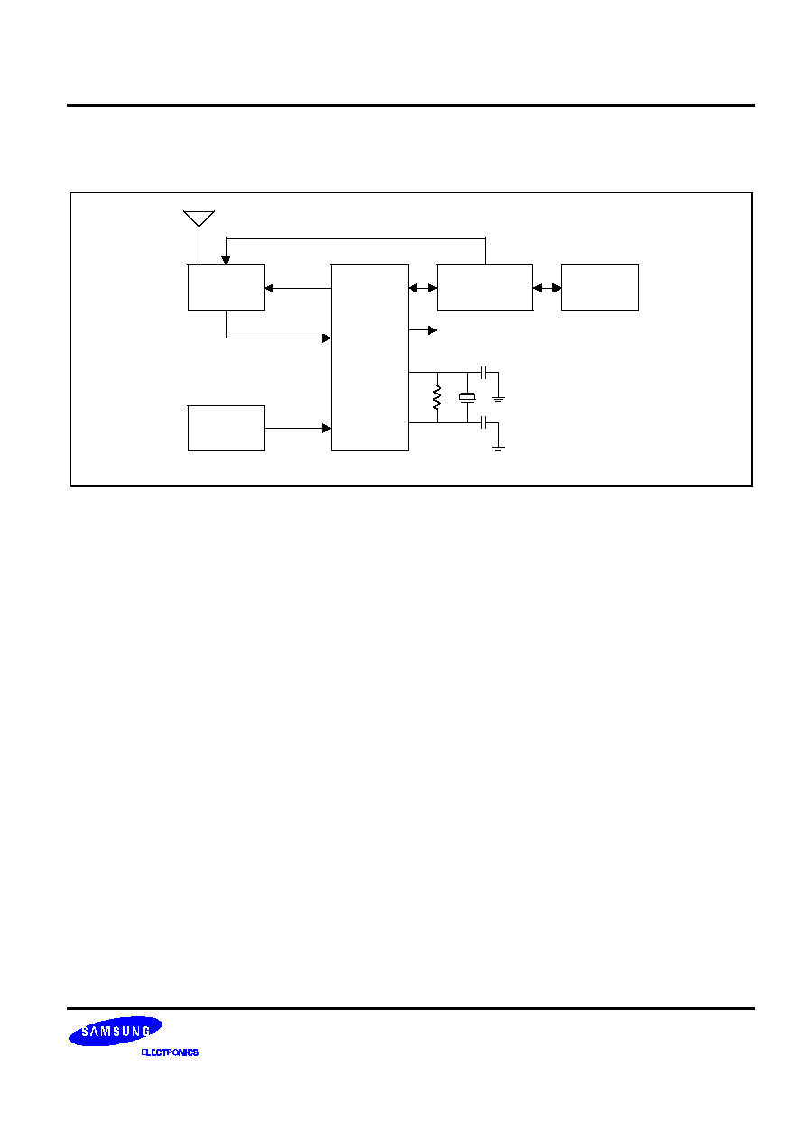
SYSTEM BLOCK DIAGRAM
Receiver
Receiver
Control
S5T8701
S0/IFIN
Programming Control
Synthesizer
Host
Microprocessor
38.4 or 40kHz Clock
LOBAT
Low Battery
Detector
10 M
160 kHz
15pF
15pF
User
Interface
Figure 1 : Example Block Diagram Using Internal Demodulator
When configured to use the internal demodulator, the S5T8701 connects to a receiver capable of generating a
limited (i.e. 1-bit digitized) 455kHz or 140kHz IF signal. In this mode, the S5T8701 has 7 receiver control lines
used for warming up and shutting down a receiver in stages. The S5T8701 has the ability to detect a low battery
signal during the receiver control sequences. It interfaces to a host MCU through a standard SPI. It has a 1minute
timer that offers low power support for a time of day function on the host.
When using the internal demodulator, the oscillator frequency (or external clock) must be 160kHz. The CLKOUT
signal can be programmed to be either a 38.4kHz signal created by fractionally dividing the oscillator clock, or a
40kHz signal creating by dividing the oscillator clock by 4.

S5T8701
FLEX
TM
ROAMING DECODER II
4
Receiver
Receiver
Control
S5T8701
Programming Control
Synthesizer
Host
Microprocessor
38.4kHz Clock
LOBAT
Low Battery
Detector
10 M
76.8 kHz
10pF
10pF
User
Interface
EXTS0
Audio to
Digital
Converter
Audio
EXTS1
Figure 2 : Example Block Diagram Using External Demodulator
The S5T8701 can also be configured to connect to a receiver capable of converting a 4 level audio signal into a 2
bit digital signal. In this mode, the S5T8701 has a 8 receiver control lines used for warming up and shutting down
a receiver in stages. It also includes configuration setting for the two post detection filter bandwidths required to
decode the two symbol rates of the FLEX signal. Also when using an external demodulator, the oscillator
frequency (or external clock) must be 76.8kHz and the CLKOUT signal (when enabled) is 38.4kHz clock output
capable of driving other devices.