S6A0032 PRELIMINARY SPEC. VER. 0.5 16 COM / 80 SEG DRIVER & CONTROLLER FOR STN LCD
2
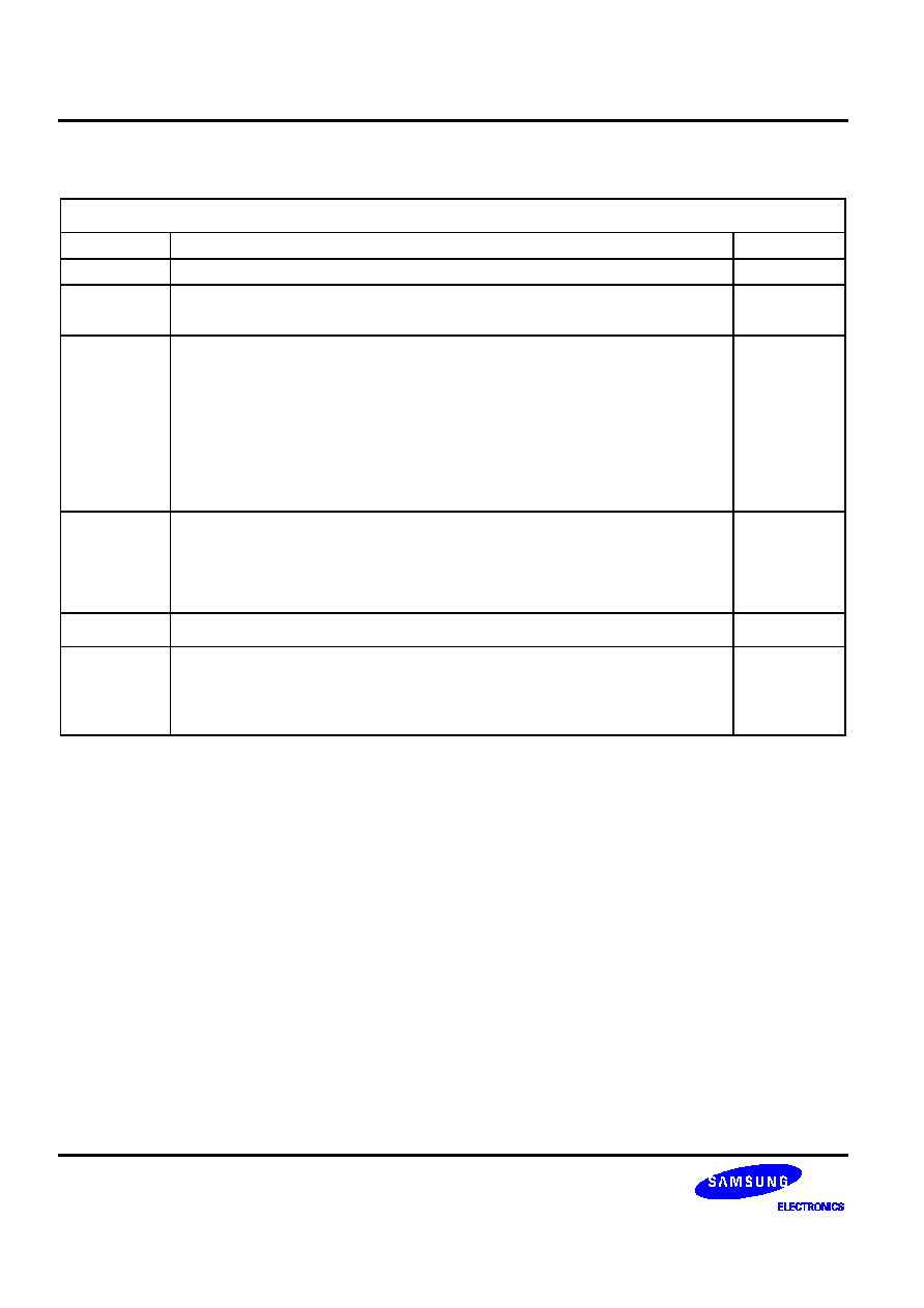
S6A0032 Specification Revision History
Version
Content
Date
0.0
Original
Feb.1999
0.1
ECKON pad added
POR circuit added
Mar.1999
0.2
Page 5: (4/5) x V0
(3/5) x V0
(3/5) x V0
(2/5) x V0
Page 6: E_RD signal description is changed
E_RD: Active low signal for writing command in 6800 mode or high enable
signal for reading command in 8080 mode.
E_RD: Active low signal for writing command or high enable signal for reading
command in 6800 mode, low enable signal for reading command in
8080 mode.
Apr.1999
0.3
Page 6: LCD DRIVER OUTPUT added
Page 18: Power ON / OFF timing added
Page 29:
I
DD1
(V
DD
= 2.4~3.6V): 150
�
A
50
�
A
Page 30:
I
DD1
(V
DD
= 3.6~5.5V): 250
�
A
80
�
A
May.1999
0.4
Page 1, 2, 11: CGROM character size is changed from 256 to 254.
Jun.1999
0.5
Page 6: RW_WR active low -> active high
Page 6: RW_WR active low -> low enable
Page 20: Wait for more than 1.2us or Busy Check -> delete " or Busy Check"
Page 21: Wait for more than 1.2us or Busy Check -> delete " or Busy Check"
Jun.1999

16 COM / 80 SEG DRIVER & CONTROLLER FOR STN LCD PRELIMINARY SPEC. VER. 0.5 S6A0032
3
CONTENTS
INTRODUCTION.......................................................................................................................................... 1
FEATURES ................................................................................................................................................. 1
BLOCK DIAGRAM ...................................................................................................................................... 2
PAD CONFIGURATION............................................................................................................................... 3
PAD CENTER COORDINATES ................................................................................................................... 4
PIN DESCRIPTION...................................................................................................................................... 5
POWER SUPPLY ................................................................................................................................. 5
SYSTEM CONTROL ............................................................................................................................ 5
MPU INTERFACE ................................................................................................................................ 6
LCD DRIVER OUTPUT ........................................................................................................................ 6
TEST.................................................................................................................................................... 6
FUNCTIONAL DESCRIPTION..................................................................................................................... 7
MICROPROCESSOR INTERFACE ...................................................................................................... 7
ADDRESS COUNTER (AC)................................................................................................................ 10
DISPLAY DATA RAM (DDRAM) ......................................................................................................... 10
CHARACTER GENERATOR ROM (CGROM)..................................................................................... 11
CHARACTER GENERATOR RAM (CGRAM) ..................................................................................... 12
LCD DRIVER CIRCUIT....................................................................................................................... 13
INSTRUCTION DESCRIPTION.................................................................................................................. 14
INITIALIZING............................................................................................................................................. 18
HARDWARE RESET .......................................................................................................................... 18
INSTRUCTION INITIALIZING WITH RESET....................................................................................... 20
LCD DRIVING POWER SUPPLY CIRCUIT................................................................................................ 22
MPU INTERFACE...................................................................................................................................... 23
INTERFACING WITH 8080-SERIES MICROPROCESSORS.............................................................. 23
INTERFACING WITH 6800-SERIES MICROPROCESSORS.............................................................. 23
APPLICATION INFORMATION FOR LCD PANEL .................................................................................... 24
FRAME FREQUENCY ............................................................................................................................... 28
MAXIMUM ABSOLUTE RATE................................................................................................................... 29
ELECTRICAL CHARACTERISTICS .......................................................................................................... 30
DC CHARACTERISTICS .................................................................................................................... 30
AC CHARACTERISTICS .................................................................................................................... 32
16 COM / 80 SEG DRIVER & CONTROLLER FOR STN LCD PRELIMINARY SPEC. VER. 0.5 S6A0032
1
INTRODUCTION
This character driver and controller LSI for liquid crystal dot matrix display systems can display 2-line of 16
characters with the 5 x 8 dots format. It is capable of interfacing various microprocessors, supporting the 4-bit or
8-bit parallel mode. Voltage follower and bias circuit is built in the IC.
FEATURES
Driver Output Circuits
-
16 common outputs / 80 segment outputs
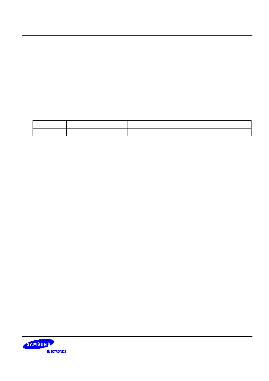
Applicable Duty Ratio
Font size
Display size
Duty
Contents of outputs
5 x 8
2-line x 16 characters
1/16
2 x 16 characters
On-chip Display Data RAM
-
Character Generator ROM (CGROM): 10,160 bits (254 characters x 5 x 8 dots)
-
Character Generator RAM (CGRAM): 80 bits (2 characters x 5 x 8 dots)
-
Display Data RAM (DDRAM): 256 bits (16 characters x 2-line)
Microprocessor Interface
-
8-bit parallel interface with 6800-series or 8080-series MPU
-
4-bit parallel interface with 6800-series or 8080-series MPU
Function Set
-
Simple instruction set
-
COM / SEG bi-directional (4 types of LCD application available)
-
Hardware reset (RESETB)
On-chip Analog Circuit
-
Internal RC oscillator circuit
-
Voltage follower & bias circuit
-
Automatic power on reset circuit
Operating Voltage Range
-
Supply voltage (V
DD
): 2.4 to 5.5V
-
LCD driving voltage (V
LCD
= V0 - V
SS
): 6.0V Max.
Low Power Consumption
Package Type
-
Gold bumped chip