S6B0721 PRELIMINARY SPEC. VER. 0.1 132 SEG / 65 COM DRIVER & CONTROLLER FOR STN LCD
3
CONTENTS
INTRODUCTION ..................................................................................................................................................1
FEATURES ..........................................................................................................................................................1
BLOCK DIAGRAM ...............................................................................................................................................3
PAD CONFIGURATION .......................................................................................................................................4
PAD CENTER COORDINATES............................................................................................................................5
PIN DESCRIPTION ..............................................................................................................................................7
POWER SUPPLY..........................................................................................................................................7
LCD DRIVER SUPPLY..................................................................................................................................7
SYSTEM CONTROL .....................................................................................................................................8
MICROPROCESSOR INTERFACE .............................................................................................................10
LCD DRIVER OUTPUTS .............................................................................................................................12
FUNCTIONAL DESCRIPTION............................................................................................................................13
MICROPROCESSOR INTERFACE .............................................................................................................13
DISPLAY DATA RAM (DDRAM) ..................................................................................................................17
LCD DISPLAY CIRCUITS............................................................................................................................20
LCD DRIVER CIRCUIT ...............................................................................................................................22
POWER SUPPLY CIRCUITS ......................................................................................................................23
REFERECE CIRCUIT EXAMPLES..............................................................................................................30
RESET CIRCUIT .........................................................................................................................................32
INSTRUCTION DESCRIPTION...........................................................................................................................33
SPECIFICATIONS..............................................................................................................................................47
ABSOLUTE MAXIMUM RATINGS...............................................................................................................47
DC CHARACTERISTICS.............................................................................................................................48
REFERENCE DATA....................................................................................................................................51
AC CHARACTERISTICS .............................................................................................................................53
REFERENCE APPLICATIONS...........................................................................................................................57
MICROPROCESSOR INTERFACE .............................................................................................................57
CONNECTIONS BETWEEN S6B0721 AND LCD PANEL ............................................................................58
TCP PIN LAYOUT (SAMPLE)......................................................................................................................63
S6B0721 PRELIMINARY SPEC. VER. 0.1 132 SEG / 65 COM DRIVER & CONTROLLER FOR STN LCD
1
INTRODUCTION
The S6B0721 is a driver & controller LSI for graphic dot-matrix liquid crystal display systems. It contains 65
commons and 132 segments driver circuits. This chip is connected directly to a microprocessor, accepts serial or
8-bit parallel display data and stores in an on-chip Display Data RAM of 65 x 132 bits. It provides a high-flexible
display section due to 1-to-1 correspondence between on-chip display data RAM bits and LCD panel pixels. And it
performs display data RAM read/write operation with no externally operating clock to minimize power
consumption. In addition, because it contains power supply circuits necessary to drive liquid crystal, it is possible
to make a display system with the fewest components.
FEATURES
Driver Output Circuits
-
65 common outputs / 132 segment outputs
On-chip Display Data RAM
-
Capacity: 65 x 132 = 8,580 bits
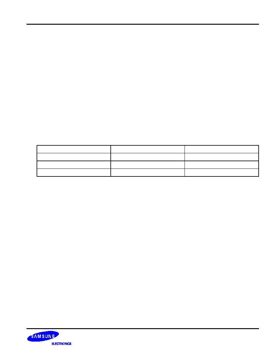
Applicable Duty Ratios
Duty ratio
Applicable LCD bias
Maximum display area
1/65
1/7 or 1/9
65
◊
132
1/49
1/6 or 1/8
49
◊
132
1/33
1/5 or 1/6
33
◊
132
Microprocessor Interface
-
8-bit parallel bi-directional interface with 6800-series or 8080-series
-
Serial interface (only write operation) available
Function Set
-
Various instructions sets
-
H/W, S/W reset capable
Built-in Analog Circuit
-
On-chip oscillator circuit
-
Voltage converter (x2, x3, x4, x5)
-
Voltage regulator (temperature coefficient: -0.05%/
∞
C, -0.2%/
∞
C)
-
Voltage follower
-
Electronic contrast control function (64 steps)
Operating Voltage Range
-
Supply voltage (V
DD
): 2.4 to 3.6 V
-
LCD driving voltage (V
LCD
= V0 - V
SS
): 4.0 to 15.0 V
Low Power Consumption
-
70
µ
Typ. (V
DD
= 3V, x4 boosting, V0 = 11V, internal power supply ON)
-
10
µ
Max. (during power save [standby] mode)
Package Type
-
Gold bump chip or TCP