139
Darlington
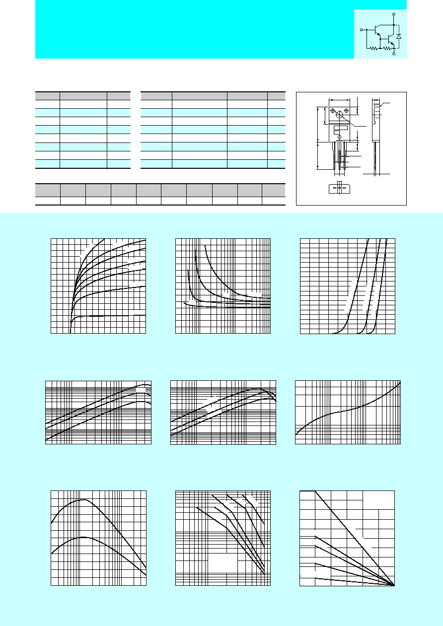
2SD2014
I
C
≠ V
C E
Characteristics (Typical)
h
F E
≠ I
C
Characteristics (Typical)
j - a
≠ t
Characteristics
0
0
1
2
4
3
2
1
3
4
C o l l e c t o r - E m i t t e r V o l t a g e V
C E
( V )
Collector Current I
C
(A)
I
B
=20mA
0 . 3 m A
1 . 0
m A
0 . 4 m A
0 . 5 m A
0 . 8 m
A
0 . 6 m
A
Safe Operating Area (Single Pulse)
4
1
0 . 1
0 . 5
0 . 0 3
50
30
500
100
1000
10000
20000
5000
C o l l e c t o r C u r r e n t I
C
( A )
DC Current Gain h
FE
( V
C E
= 4 V )
1 0
5 0
3
5
1 0 0
0 . 0 5
0 . 1
1
0 . 5
1 0
5
C o l l e c t o r - E m i t t e r V o l t a g e V
C E
( V )
Collector Current I
C
(A)
Without Heatsink
Natural Cooling
DC
100ms
10ms
1ms
0 . 5
1
5
1
1 0
1 0 0
1 0 0 0
5
5 0
5 0 0
T i m e t ( m s )
Transient Thermal Resistance
j-a
(∞C/W)
T y p
V
C E
( s a t ) ≠ I
B
Characteristics (Typical)
0
3
2
1
0 . 2
5
1 0
1
1 0 0
5 0
B a s e C u r r e n t I
B
( m A )
Collector-Emitter Saturation Voltage V
CE(sat)
(V)
I
C
= 4 A
2 A
1 A
3 A
300
µ
s
I
C
≠ V
B E
Temperature
Characteristics (Typical)
0
2
1
B a s e - E m i t t o r V o l t a g e V
B E
( V )
Collector Current I
C
(A)
( V
C E
= 4 V )
0
3
4
2
1
125∞C (Case Temp)
25∞C (Case Temp)
≠30∞C (Case Temp)
h
F E
≠ I
C
Temperature
Characteristics (Typical)
C o l l e c t o r C u r r e n t I
C
( A )
DC Current Gain h
FE
0 . 0 3
0 . 5
1
4
0 . 1
100
50
30
500
1000
5000
10000
20000
( V
C E
= 4 V )
1 2
5 ∞ C
25∞C
≠30∞C
f
T
≠ I
E
Characteristics (Typical)
≠ 0 . 0 2
≠ 0 . 0 5 ≠ 0 . 1
≠ 0 . 5
≠ 1
≠ 4
0
2 0
4 0
1 2 0
1 0 0
6 0
8 0
Cut-off Frequency f
T
(MH
Z
)
( V
C E
= 1 0 V )
E m i t t e r C u r r e n t I
E
( A )
T y p
P c ≠ T a Derating
2 5
2 0
1 0
2
0
0
2 5
5 0
7 5
1 0 0
1 2 5
1 5 0
A m b i e n t T e m p e r a t u r e T a ( ∞ C )
Maximum Power Dissipation P
C
(W)
With Infinite heatsink
Without Heatsink
1 5 0 x 1 5 0 x 2
5 0 x 5 0 x 2
1 0 0 x1 00
x2
Natural Cooling
Silicone Grease
Heatsink: Aluminum
in mm
Silicon NPN Triple Diffused Planar Transistor
(Complement to type 2SB1257)
Application : Driver for Solenoid, Relay and Motor, Series Regulator, and General Purpose
Symbol
V
CBO
V
CEO
V
EBO
I
C
I
B
P
C
Tj
T
stg
2SD2014
120
80
6
4
0.5
25(Tc=25∞C)
150
≠55 to +150
Unit
V
V
V
A
A
W
∞C
∞C
s
Absolute maximum ratings
s
Electrical Characteristics
2SD2014
10
max
10
max
80
min
2000
min
1.5
max
2.0
max
75
typ
45
typ
Unit
µ
A
mA
V
V
V
MHz
pF
Conditions
V
CB
=120V
V
EB
=6V
I
C
=10mA
V
CE
=2V, I
C
=3A
I
C
=3A, I
B
=3mA
I
C
=3A, I
B
=3mA
V
CE
=12V, I
E
=≠0.1A
V
CB
=10V, f=1MHz
(Ta=25∞C)
(Ta=25∞C)
Symbol
I
CBO
I
EBO
V
(BR)CEO
h
FE
V
CE
(sat)
V
BE
(sat)
f
T
C
OB
External Dimensions FM20(TO220F)
¯3.3
±0.2
10.1
±0.2
4.0
±0.2
16.9
±0.3
13.0min
8.4
±0.2
0.8
±0.2
3.9
±0.2
2.54
2.54
1.35
±0.15
0.85
+0.2
-0.1
1.35
±0.15
2.2
±0.2
4.2
±0.2
2.8
c0.5
2.4
±0.2
0.45
+0.2
-0.1
B
E
C
a
b
s
Typical Switching Characteristics (Common Emitter)
V
CC
(V)
30
R
L
(
)
10
I
C
(A)
3
V
BB2
(V)
≠5
I
B2
(mA)
≠10
t
on
(
µ
s)
1.0typ
t
stg
(
µ
s)
4.0typ
t
f
(
µ
s)
1.5typ
I
B1
(mA)
10
V
BB1
(V)
10
Weight : Approx 2.0g
a. Type No.
b. Lot No.
B
C
E
(3k
) (200
)
Equivalent
circuit