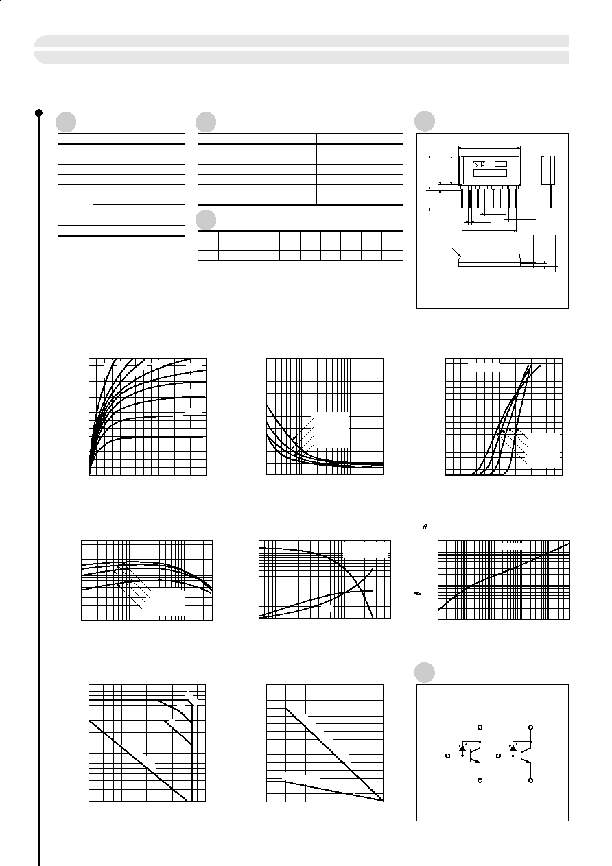
Absolute Maximum Ratings
Electrical Characteristics
Typical Switching Characteristics
0
1
2
3
s
I
C
-- V
CE
Characteristics (typ.)
0
2
I
C
(A)
V
CE
(V)
1
3
0
2
1
4
3
0
0.5
1.0
1.5
s
I
C
-- V
BE
Temperature Characteristics (typ.)
I
C
(A)
V
BE
(V)
0.01
0.05
0.1
3
0.5
1
s
h
FE
-- I
C
Temperature Characteristics (typ.)
100
h
FE
I
C
(A)
5000
1000
500
0.1
0.05
0.5
1
5
s
t
on∑
t
stg∑
t
f
-- I
C
Characteristics (typ.)
0.3
0.5
5
1
10
t
on
∑
t
stg
∑
t
f
(
µ
S)
Ic (A)
20
2
5
10
50
s
Safe Operating Area (single pulse)
0.5
0.2
1
5
I
C
(a)
V
CE
(V)
10
(per element)
0.002
0.01
0.05 0.1
0.4
s
V
CE
(sat) -- I
B
Temperature Characteristics
0
0.5
1
V
CE
(sat)
(V)
I
B
(A)
I
B
=1mA
2mA
3mA
V
CE
=
12V
I
B1
= ≠
I
B2
=
5mA
V
CE
=
4V
(I
C
=
1A)
(V
CE
=
4V)
0
50
150
100
s
P
T
-- Ta Derating
0
10
5
P
T
(W)
Ta (∫C)
15
Ta
= ≠
55∫C
25∫C
75∫C
125∫C
10ms
1ms
100m
Ta
=
125∫C
75∫C
25∫C
≠55∫C
0.1
1
10
100
1000
5000
s
j-a
-- t Characteristics
0.1
0.5
1
5
10
j-a
(∫C/W)
t (ms)
20
Single pulse
15mA 1
0m
A
8mA
6mA
5mA
4mA
Ta
=
125∫C
75∫C
25∫C
≠55∫C
t
stg
t
f
t
on
Without heatsink (All circuits operate)
With infinite heatsink (All circuits operate)
DC (Tc
=2
5∫C)
Symbol
Ratings
Unit
(Ta=25∫C)
(Ta=25∫C)
V
CBO
35
±
5
Symbol
Test Conditions
Ratings
Unit
I
CBO
µ
A
V
CB
= 30V
10max
I
EBO
µ
A
V
EB
= 6V
10max
V
CEO
V
I
C
= 25mA
35
±
5
h
FE
V
CE
= 4V, I
C
= 0.5A
500min
V
CE
(sat)
V
I
C
= 1A, I
B
= 5mA
0.5max
Es/b
mJ
L = 10mH, single pulse
150min
V
CEO
V
V
35
±
5
V
EBO
V
6
I
C
A
3
2.5 (Ta=25∫C)
12 (Tc=25∫C)
I
B
A
1
P
T
W
W
Tj
∫C
150
Tstg
∫C
≠55 to +150
12
V
CC
(V)
12
R
L
(
)
1
I
C
(A)
10
V
BB1
(V)
≠5
V
BB2
(V)
5
I
B1
(mA)
5
I
B2
(mA)
1.3
t
on
(
µ
s)
4.7
t
stg
(
µ
s)
1.2
t
f
(
µ
s)
2
4
3
7
5
6
Power Transistor Array STA335A
63
Equivalent Circuit Diagram
a) Type No.
b) Lot No.
(Unit: mm)
a
b
7∑2.54=17.78
±
0.25
(2.54)
20.2
±
0.2
0.5
±
0.15
1.0
±
0.25
C1.5
±
0.5
4.0
±
0.2
1.
2
±
0.2
0.5
±
0.15
1
3
2
4
C
B
E
5
6
7
8
E
B
C
9.0
±
0.2
2.3
±
0.2
11.3
±
0.2
4.7
±
0.5
External Dimensions
STA3 (LF400A)