 | –≠–ª–µ–∫—Ç—Ä–æ–Ω–Ω—ã–π –∫–æ–º–ø–æ–Ω–µ–Ω—Ç: STR9012 | –°–∫–∞—á–∞—Ç—å:  PDF PDF  ZIP ZIP |
66
Parameter
Input Voltage
Output Voltage
Dropout Voltage
Line Regulation
Load Regulation
Temperature Coefficient of Output Voltage
Ripple Rejection
Overcurrent Protection
Starting Current
Output ON/OFF Control Voltage
(Voltage between terminal No.3 and 5)
Voltage with Output Off
Symbol
V
IN
I
O
P
D1
P
D2
T
j
T
op
T
stg
R
th(j-c)
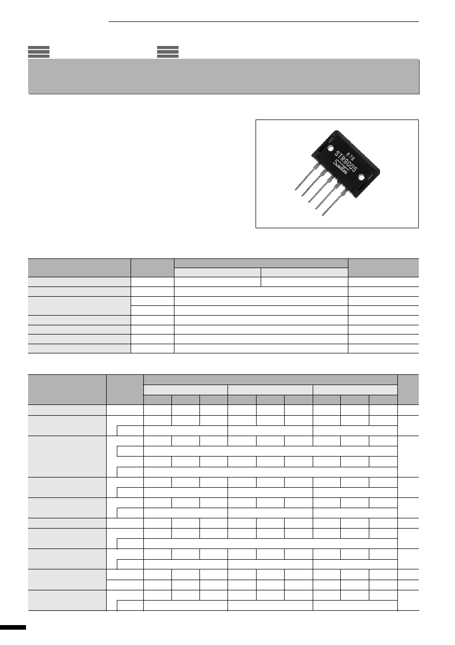
STR9000 Series
5-Terminal, Low Dropout Voltage Dropper Type
(T
a
=25
∞
C)
s
Electrical Characteristics
Unit
V
V
V
mV
mV
mV/
∞
C
dB
A
V
V
V
(T
a
=25
∞
C)
*Output is turned on when voltage between terminal No.3 and 5 is less than 0.6V, and turned off if more than 2.0V.
Symbol
V
IN
V
O
Conditions
V
DIF
Conditions
Conditions
V
OLINE
Conditions
V
OLOAD
Conditions
V
O
/
T
a
R
REJ
Conditions
I
S1
Conditions
V
O
(ON)
V
O
(OFF)
V
O
Conditions
Ratings
STR9005
STR9012
STR9015
min.
typ.
max.
min.
typ.
max.
min.
typ.
max.
6
15
13
25
16
25
4.9
5.0
5.1
11.8
12.0
12.2
14.8
15.0
15.2
V
IN
=8V, I
O
=2.0A
V
IN
=16V, I
O
=2.0A
V
IN
=20V, I
O
=2.0A
0.5
0.5
0.5
I
O
=2.0A
1.0
1.0
1.0
I
O
=4.0A
10
30
30
80
50
100
V
IN
=6 to 15V, I
O
=2.0A
V
IN
=13 to 25V, I
O
=2.0A
V
IN
=16 to 25V, I
O
=2.0A
40
100
80
200
100
200
V
IN
=8V, I
O
=0 to 3.0A
V
IN
=16V, I
O
=0 to 3.0A
V
IN
=20V, I
O
=0 to 3.0A
±
0.5
±
1.5
±
1.5
54
54
54
f=100 to 120H
Z
4.1
4.1
4.1
V
IN
=8V
V
IN
=16V
V
IN
=20V
0.6
0.6
0.6
2.0
2.0
2.0
0.5
0.5
0.5
V
IN
=8V, I
O
=0A
V
IN
=15V, I
O
=0A
V
IN
=20V, I
O
=0A
s
Features
∑ 5-terminal regulator with two screw mount package
∑ Output current: 4.0A
∑ Low dropout voltage :V
DIF
1V (at I
O
=4A)
∑ Fine adjustment of output voltage
∑ Output ON/OFF control
∑ Built-in foldback overcurrent protection circuits
s
Applications
∑ For stabilization of the secondary stage of switching power supplies
∑ Electronic equipment
s
Absolute Maximum Ratings
Unit
V
V
W
W
∞
C
∞
C
∞
C
∞
C/W
Ratings
STR9005
STR9012/9015
25
30
4.0
75(T
C
=25
∞
C)
3.2(Without heatsink, stand-alone operation)
≠30 to +125
≠20 to +100
≠30 to +125
1.25
q
STR9000 Series
Parameter
DC Input Voltage
DC Output Current
Power Dissipation
Junction Temperature
Ambient Operating Temperature
Storage Temperature
Thermal Resistance (junction to case)
67
s
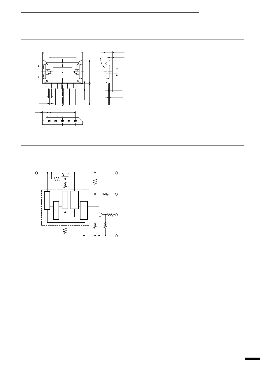
Outline Drawing
(unit:mm)
Plastic Mold Package Type
Flammability: UL94V-0
Weight: Approx. 14.5g
Terminal Connections
q
Output (backside of case)
w
Output Fine Adjustment
e
Output ON/OFF Control
r
Input
t
Ground
s
Block Diagram
4
1
2
3
5
M
Tr
1
Tr
2
R
2
R
1
R
4
R
6
R
7
R
8
R
5
R
3
Reg.
Protection
Drive
Amp.
V
REF
q
STR9000 Series
36.0
±
0.3
2.0
±
0.2
24.4
±
0.2
5.45
◊
4
2.0
3.0
30
∞
3.5
5.45
1.0
+0.2
≠0.1
0.6
+0.2
≠0.1
12.0
±
0.3
21.2
±
0.3
3.2
±
0.1
4.7max.
6.0max.
20.0min.
q
w
e
r
t
Part Number
Lot Number
68
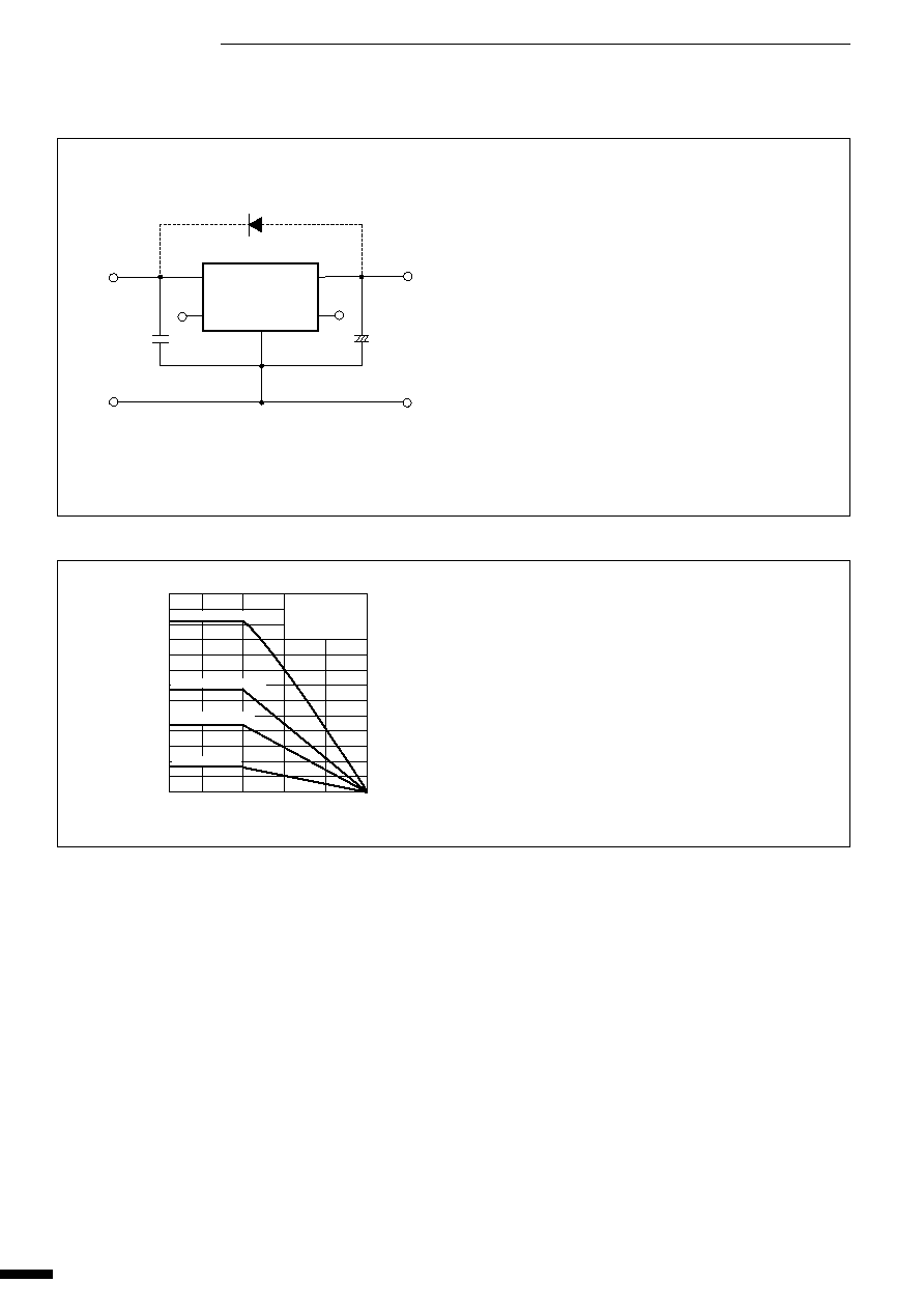
s
T
a
-P
D
Characteristics
s
Standard External Circuit
C
1
: Oscillation prevention capacitor (approx. 0.33
µ
F)
Connection to terminal No.4 must be made as short as
possible.
C
2
: Output capacitor (47 to 100
µ
F)
Connection to terminal No.1 must be made as short as
possible.
D
1
: Protection diode (RM1Z)
Required for protection against reverse biasing of input
and output.
Note 1: Prevention of oscillation at low temperatures
At low temperatures, oscillation may occur unless an
output capacitor with good tan
is used. Be sure to
connect a tantalum capacitor (approx. 10
µ
F) in par-
allel with output capacitor C
2
.
Note 2: An isolation type diode is provided from input to
ground and also from output to ground. These may
be destroyed if the device is reverse biased. In this
case, use a diode with low V
F
to protect them.
q
STR9000 Series
V
IN
V
O
D
1
C
2
C
1
3
2
4
1
5
STR9000
+
DC input
DC output
24
20
16
12
8
4
0
≠20
0
25
Ambient Temperature T
a
(
∞
C)
Power Dissipation P
D
(W)
50
75
100
150
◊
150
◊
2(3.3
∞
C/W)
100
◊
100
◊
2(5.2
∞
C/W)
75
◊
75
◊
2(7.6
∞
C/W)
Without heatsink
Without Mica
With Slicon Grease
Heatsink: Aluminum
Unit: mm
69
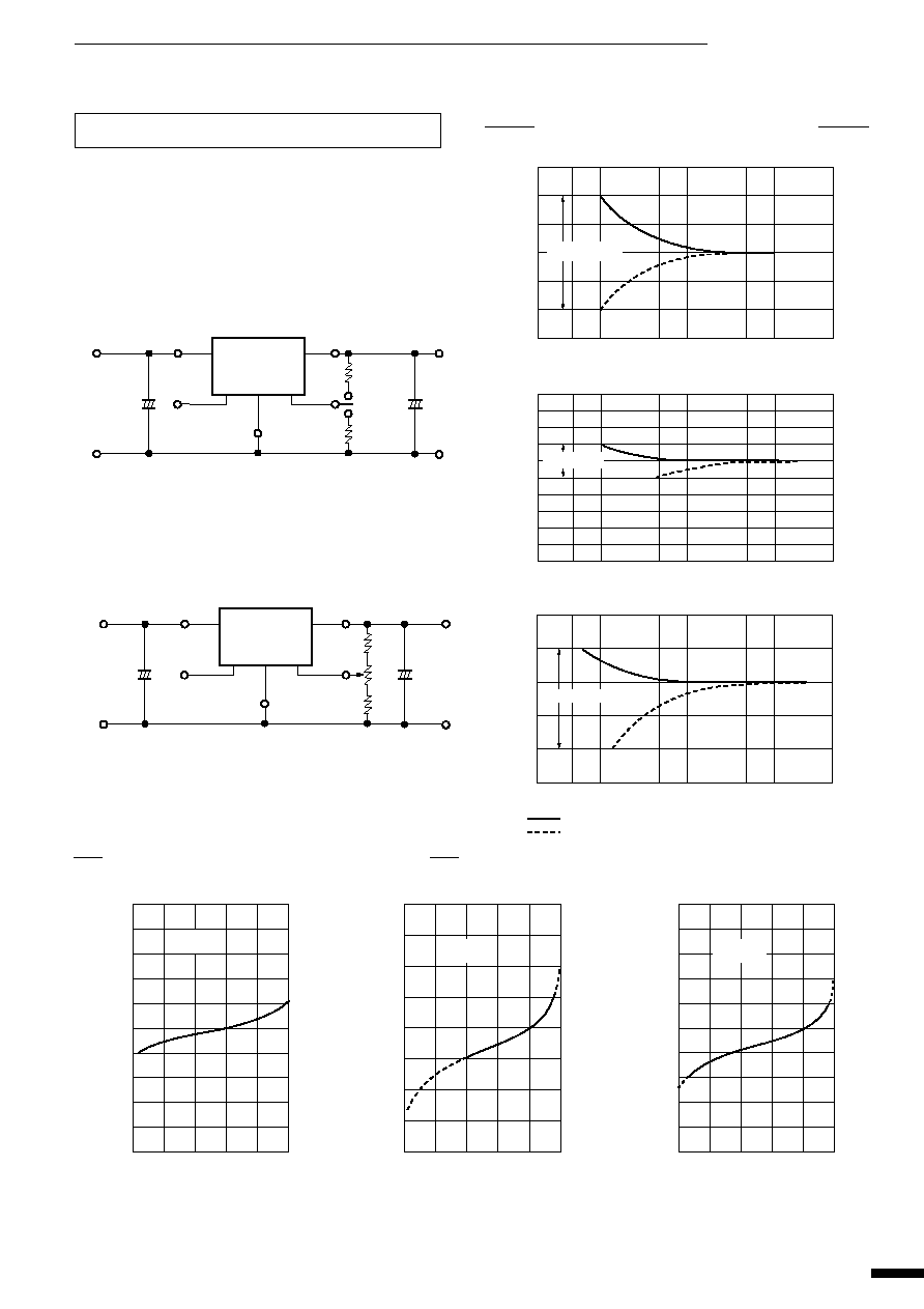
External Variable Output Voltage Circuit
1. Variable output voltage with a single external resistor
The output voltage of the STR9000 series may be decreased by insert-
ing a resistor between terminals No.1 (output terminal) and No.2 (out-
put fine adjustment terminals). Alternatively, the output voltage may be
increased by inserting a resistor between terminals No.2 and No.5
(ground terminal).
<Standard External Circuit>
2. Fine adjustment of output voltage
The output voltage may be finely adjusted by using terminals No.1, No.2
and No. 5 as shown in the following connections.
<Standard External Circuit>
Note: The fine adjustment range of output voltage for the STR9000 se-
ries is
±
0.5V max for STR9012 and +1.0V/-2.0V max for STR9015.
Adjustment exceeding these values may cause start-up errors.
w
Typical Characteristics of Fine Output Voltage Adjustment
q
Typical Characteristics of Variable Output Voltage
1
4
3
5
2
STR9000
V
IN
GND
V
O
GND
R
EX
for Vo down
R
EX
for Vo up
+
+
Select either one of the external resistor.
1
4
3
5
2
STR9000
V
IN
GND
V
O
R
1
R
2
VR
GND
+
+
20K
50K 100K
500K
1M
5M
50M
10M
5.3
5.2
5.1
5.0
4.9
4.8
4.7
STR9005
External Resistor R
EX
(
)
Output Voltage V
O
(V)
(T
a
=25
∞
C)
Variable Output
Voltage Range
20K
50K 100K
500K
1M
5M
50M
10M
14
13
12
11
10
9
External Resistor R
EX
(
)
Output Voltage V
O
(V)
(T
a
=25
∞
C)
STR9012
Variable Output
Voltage Range
20K
50K 100K
500K
1M
5M
50M
10M
17
16
15
14
13
12
External Resistor R
EX
(
)
: Insertion of resistor between terminals No. 2 and No. 5
: Insertion of resistor between terminals No. 2 and No. 1
Output Voltage V
O
(V)
(T
a
=25
∞
C)
STR9015
Variable Output Voltage Range
STR9005
0
100
200
300
400
500
5.4
5.2
5.0
4.8
4.6
V
R
(k
)
Output Voltage V
O
(V)
R
1
=150 k
R
2
=150 k
(T
a
=25
∞
C)
0
100
200
300
400
500
14
13
12
11
10
V
R
(k
)
Output Voltage V
O
(V)
(T
a
=25
∞
C)
R
1
=100 k
R
2
= 30 k
STR9012
0
100
200
300
400
500
20
18
16
14
12
10
V
R
(k
)
Output Voltage V
O
(V)
(T
a
=25
∞
C)
R
1
=100 k
R
2
= 20 k
STR9015
q
STR9000 Series
70
s
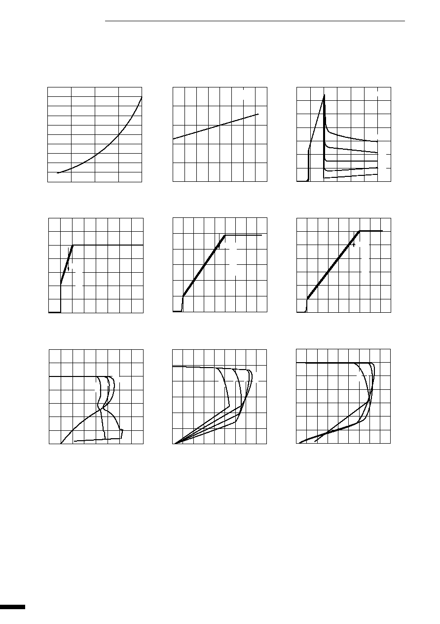
Typical Characteristics
I
O
vs. V
DIF
Characteristics
Temperature Coefficient of Output Voltage(STR9005)
Circuit Current(STR9005)
Rise Characteristics(STR9005)
Rise Characteristics(STR9012)
Rise Characteristics(STR9015)
Overcurrent Protection Characteristics(STR9005)
Overcurrent Protection Characteristics(STR9012)
Overcurrent Protection Characteristics(STR9015)
≠20
0
20
40
60
80
100 120 140
5.04
5.02
5.00
4.98
4.96
4.94
Ambient Temperature T
a
(
∞
C)
Output Voltage V
O
(V)
V
IN
=8V
l
O
=10mA
0
5
10
15
17.5
70
60
50
40
30
20
10
0
Ground Current l
G
(mA)
V
O
=5V
l
O
=4A
3A
2A
1A
0A
Input Voltage V
IN
(V)
0
5
10
15
20
7
6
5
4
3
2
1
0
Input Voltage V
IN
(V)
Output Voltage V
O
(V)
l
O
=0A
1A
2A
3A
4A
l
O
=0A
1A
2A
3A
4A
0
5
10
20
15
22.5
15
10
5
0
Input Voltage V
IN
(V)
Output Voltage V
O
(V)
l
O
=0A
1A
2A
3A
4A
0
5
10
20
15
22.5
Input Voltage V
IN
(V)
Output Voltage Vo (V)
17.5
15
10
5
0
l
O
=0A
1A
2A
3A
4A
0
1
2
3
4
5
6
7
8
7
6
5
4
3
2
1
0
Output Current l
O
(A)
Output Voltage V
O
(V)
V
IN
=6V
8V
15V
0
1
2
3
4
5
6
7
9
8
15
10
5
0
Output Current l
O
(A)
Output Voltage V
O
(V)
V
IN
=13V
16V
20V
25V
0
1
2
3
4
5
6
7
9
8
17.5
15
10
5
0
Output Current l
O
(A)
Output Voltage V
O
(V)
25V
V
IN
=16V
20V
(T
a
=25
∞
C)
q
STR9000 Series
0
1.0
3.0
3.0
4.0
1.0
0.8
0.6
0.4
0.2
0
Output Current l
O
(A)
Dropout Voltage V
DIF
(V)