50 Seaview Blvd. Port Washington, NY 11050-4618 PH.(516)625-1313 FAX(516)625-8845 E-mail: semi@sanrex.com
QCA100A/QBB100A40/60
TRANSISTOR MODULE
UL;E76102
M
Maximum Ratings
Tj25 unless otherwise specified
Electrical Characteristics
Symbol
Item
Conditions
Ratings
QCA100A40
QBB100A40
QCA100A60
QBB100A60
Unit
V
CBO
Collector-Base Voltage
400
600
V
V
CEX
Collector-Emitter Voltage
V
BE
-2V
400
600
V
Emitter-Base Voltage
V
V
EBO
10
I
C
Collector Current
pw1ms
100
200
A
-I
C
Reverse Collector Current
100
A
I
B
Base Current
6
A
P
T
Total power dissipation
T
C
25
620
W
T
j
Junction Temperature
-40 to 150
Tstg
Storage Temperature
-40 to 125
V
ISO
Isolation Voltage
A.C.1minute
2500
V
Mounting
Torque
Mounting
M5
Terminal
M5
Recommended Value 1.5-2.5
15-25
2.7
28
Recommended Value 1.5-2.5
15-25
2.7
28
N
m
(
fB)
Mass
QCA100A/QBB100A
Typical Value
360/340
g
Unit
A
Symbol
Item
Conditions
Ratings
Min.
Max.
1.0
400
75/100
2.0
2.5
2.0
Unit
I
CBO
Collector Cut-off Current
V
CB
V
CBO
mA
I
EBO
Emitter Cut-off Current
V
EB
V
EBO
mA
300
V
CEO
SUS
Collector Emitter
Sustaning Voltage
QCA100A40
QBB100A40
QCA100A60
QBB100A60
QCA100A40
QBB100A40
QCA100A60
QBB100A60
Ic
1A
V
450
400
V
CEX
SUS
Ic
20AI
B2
-5A
V
600
h
FE
DC Current Gain
Ic
100AV
CE
2V/5V
V
CE(sat)
Collector-Emitter Saturation Voltage
Ic
100AI
B
1.4A
V
V
BE(sat)
Base-Emitter Saturation Voltage
Ic
100AI
B
1.4A
V
s
ton
On Time
Vcc
300VIc100A
I
B1
2AI
B2
-2A
Switching Time
95max
62max
48
�
0
.25
M5�10
30max
110Tab
7
21
30
80�0.25
C
2
B
2
X
X
B
1
E
1
E
2
C
1
23
23
6
45.5
B
2
E
2
E
2
B
2
12
6
NAME PLATE
102.0max
63.0�0.2
3.0
1
5
.
0
6
.0
8.0
4.0
4
.0
2
.0
5.0
25.5
26.5
33.5max
32.0
15.8
B1
C1
E1
C2
E2
B2
15.8
6-M5
4-5.4
40.0
52.0
�
0.2
68.0max
15.8
1.5
3.4
10.5
15.8 15.8
C1
B1
C2E1
B2
E2
B2X
C2
B2
E2
C1
B1
E1
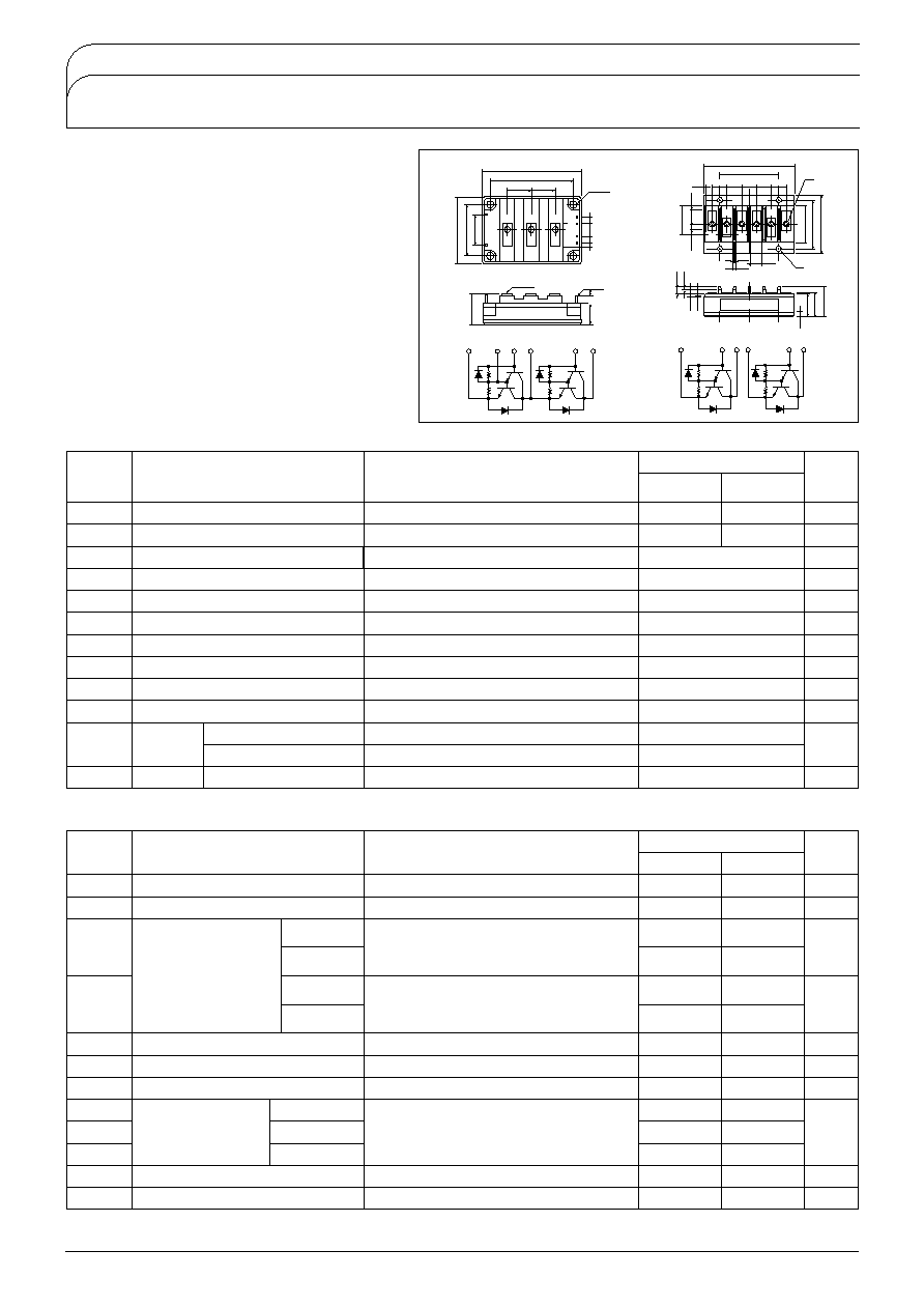
QCA
QBB
QCA100A and QBB100A is a dual Darlington power
transistor modules with two high speed, high power
Darlington transistors. Each transistor has a reverse
paralleled fast recovery diode.
QCA100A
...Series-connected type
QBB100A
...Separate Type
I
C
100A, V
CEX
400/600V
Low saturation voltage for higher efficiency.
Isolated mounting base
V
EBO
10V for faster switching speed.
Applications
Motor Control
VVVF
, AC/DC Servo, UPS,
Switching Power Supply, Ultrasonic Application
Thermal Impedance
12.0
0
3.0
0
1.4
0
0.2/0.6
V
/W
Storage Time
Fall Time
ts
tf
-Ic100A
Transistor part
Diode part
V
ECO
Rth(j-c)
Collector-Emitter Reverse Voltage
SanRex
�
SanRex 50 Seaview Blvd. Port Washington, NY 11050-4618 PH.(516)625-1313 FAX(516)625-8845 E-mail: semi@sanrex.com
QCA100A/QBB100A40/60
Typical
V
CE
5V
V
CE
2V
Tj
25
Tj
125
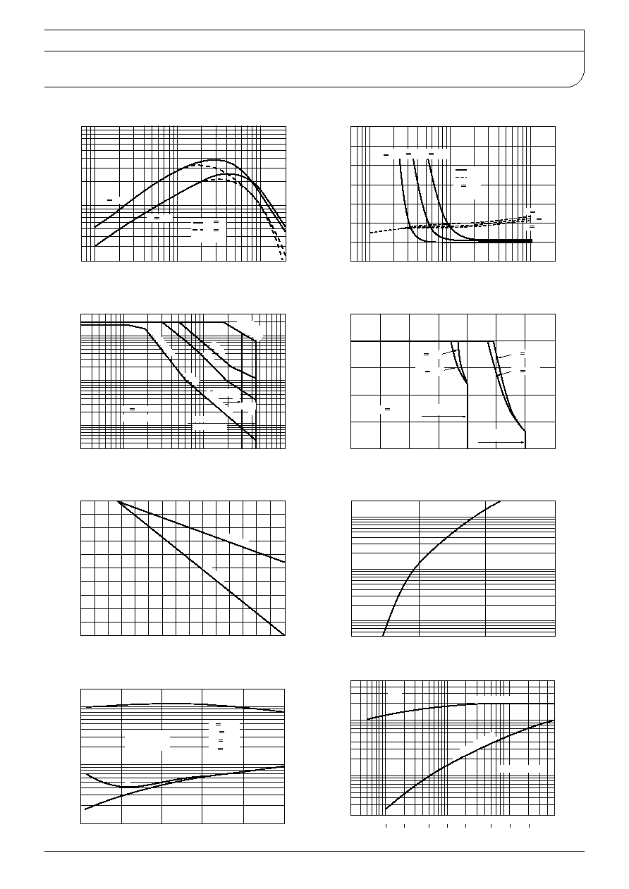
D.C. Current Gain
Collector Current IcA
DC Current Gain h
FE
I
C
80A
Typical
V
CE
V
BE
Tj
25
I
C
100A
I
C
80A
I
C
60A
I
C
100A
I
C
60A
-
Saturation Characteristics
Base Current I
B
A
Collector-Emitter Voltage V
V
Base-Emitter Voltage V
BE
V
IS/B Limited
10ms
P
T
Limited
1ms
500
s
Pulse W
ide
100
s
QCA100A
40
QBB100A
40
QCA100A60
QBB100A60
Tc
25
Non-Repetitive
Forward Bias Safe Operating Area
Collector-Emitter Voltage V
CE
V
Collector Current Ic
A
IB
2
-2A
IB
2
-5A
IB
2
-2A
IB
2
-5A
QCA100A60
QBB100A60
QCA100A40
QBB100A40
Tj
125
Reverse Bias Safe Operating Area
Collector-Emitter Voltage V
CE
V
Collector Current Ic
A
Collector Current Derating Factor
Case Temperature
Derating Factor
%
IS/B L
imite
d
P
T
Lim
ite
d
=
Maximum
Forward Voltage of Free Wheeling Diode
Emitter-Collector Voltage V
ECO
V
Collector Reverse Current -Ic
A
Typical
ts
ton
ton: On Time
ts : Storage Time
tf : Fall Time
tf
Tj
25
Vcc
300V
IB
2
2A
IB
2
-2A
-
Collector Current Vs Switching Time
Collector Current IcA
Switching Time
t
on
t
f ts
s
Junction to Case
100
sec
50msec
Junction to Case
50msec50sec
Max.
-
-
Maximum Transient Thermal Impedance
Characteristics
Time
t
sec
Transient Thermal Impedance
j-c
/
W