B1
B2
E2
E2
C2E1
B2X
B1X
E1
C1
50 Seaview Blvd. Port Washington, NY 11050-4618 PH.(516)625-1313 FAX(516)625-8845 E-mail: semi@sanrex.com
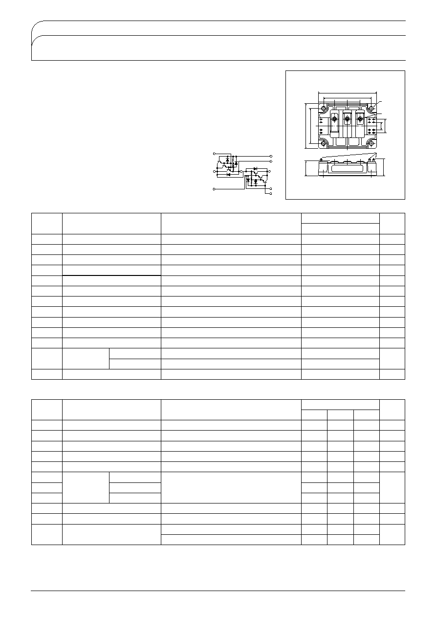
QCA300BA60
TRANSISTOR MODULE
Hi-
UL;E76102
M
Thermal Impedance
(junction to case)
Maximum Ratings
Tj25 unless otherwise specified
Electrical Characteristics
Symbol
Item
Conditions
Ratings
QCA300BA60
Unit
V
CBO
Collector-Base Voltage
600
V
V
CEX
Collector-Emitter Voltage
V
BE
-2V
600
V
V
CEX
sus
Collector-Emitter sustaining voltage
I
C
60V I
B2
-5A
600
V
Emitter-Base Voltage
V
V
EBO
10
I
C
Collector Current
pw1ms
300
600
A
-I
C
Reverse Collector Current
300
A
I
B
Base Current
18
A
P
T
Total power dissipation
T
C
25
1380
W
T
j
Junction Temperature
-40 to 150
Tstg
Storage Temperature
-40 to 125
V
ISO
Isolation Voltage
A.C.1minute
2500
V
Mounting
Torque
Mounting
M6
Terminal
M6
Recommended Value 2.5-3.9
25-40
4.7
48
Recommended Value 2.5-3.9
25-40
4.7
48
N
m
(
fB)
Mass
Typical Value
675
g
46.5
25
25
31.5
3-M6
Tab110
t =0.5
27
34.5
NAME PLATE
15
E2
B2
B1
E1
93�0.2
90max.
31max.
70
�
0
.2
B2X
B1X
113max
C2E1
E2
C
Unit
A
Symbol
Item
Conditions
Ratings
Min.
Max.
4.0
500
750
2.5
3.0
2.0
8.0
2.0
2.2
0.08
0.35
Unit
I
CBO
Collector Cut-off Current
V
CB
V
CBO
mA
I
EBO
Emitter Cut-off Current
V
EB
V
EBO
mA
h
FE
D.C. Current Gain
Ic
300AV
CE
2.5V
V
CE
sat
Collector-Emitter Saturation Voltage
Ic
300AI
B
400mA
V
V
BE
sat
Base-Emitter Saturation Voltage
Ic
300AI
B
400mA
V
s
V
/W
ton
On Time
Storage Time
Fall Time
Transistor part
Diode part
ts
tf
Vcc
300VIc300A
I
B1
0.6AI
B2
-6A
Ic
-300A
V
ECO
Rth
j-c
Switching
Time
Collector-Emitter Reverse Voltage
Typ.
200
ns
Vcc
300V, Ic-300A, -di/dt300A/s, V
BE
-5V
trr
Reverse Recovery time
QCA300BA60 is a dual Darlington power transistor module which has series-connected
ULTRA HIGH h
FE
, high speed, high power Darlington transistor. Each transistor has a
reverse paralleled fast recovery diode (trr
200ns). The mounting base of the module is
electrically isolated from semiconductor elements for simple heatsink construction,
I
C
300A, V
CEX
600V
Low saturation voltage for higher efficiency.
ULITRA HIGH DC current gain h
FE
. h
FE
750
Isolated mounting base
V
EBO
10V for faster switching speed.
Applications
Motor Control
VVVF
, AC/DC Servo, UPS,
Switching Power Supply, Ultrasonic Application
SanRex
�
SanRex 50 Seaview Blvd. Port Washington, NY 11050-4618 PH.(516)625-1313 FAX(516)625-8845 E-mail: semi@sanrex.com
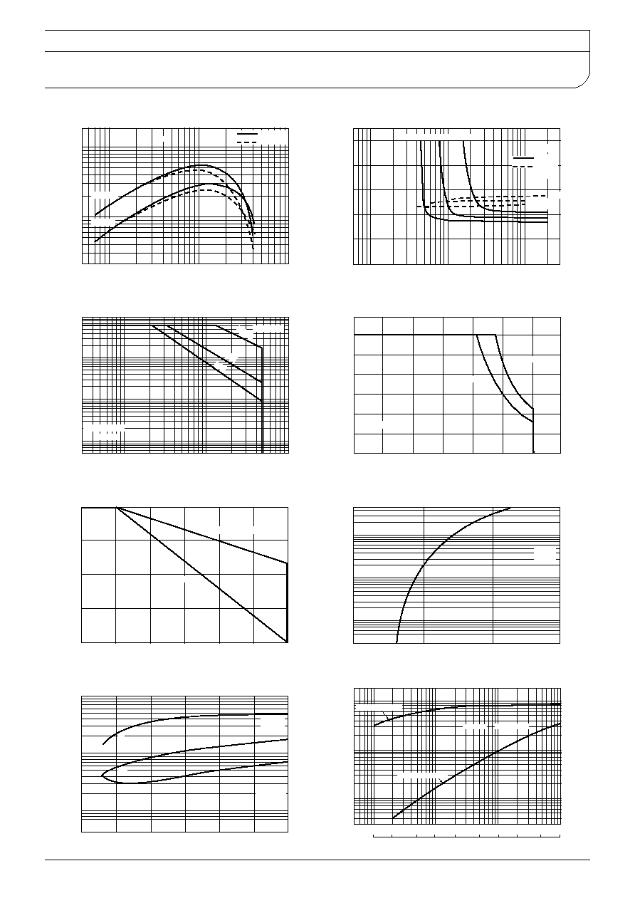
QCA300BA60
Tj125
Tj25
Typical
V
CE
5V
V
CE
2.5V
D.C. Current Gain
Collector Current IcA
DC Current Gain h
FE
Ic120A Ic200A Ic300A
Typical
V
CE
sat
V
BE
sat
Tj25
Ic300A
Ic200A
Ic120A
Saturation Characteristics
Base Current I
B
A
-
-
Collector-Emitter Voltage V
V
Base-Emitter Voltage V
BE
V
Non-Repetitive
Tc25
500
s
100
s
1s
Pulse Wide
Forward Bias Safe Operating Area
Collector-Emitter Voltage V
CE
V
3
Collector Current Ic
A
Tj125
I
B2
-10A
I
B2
-3.5A
Reverse Bias Safe Operating Area
Collector-Emitter Voltage V
CE
V
Collector Current Ic
A
Collector Current Derating Factor
Case Temperature
Derating Factor
%
Second Breakdown Limit
Thermal Limit
Typical
Tj25
Forward Voltage of Free Wheeling Diode
Emitter-Collector Voltage V
ECO
V
Collector Reverse Current -Ic
A
Typical
Tj25
tf
ts
ton
I
B1
0.6A
I
B2
-6.0A
V
CC
300V
Collector Current Vs Switching Time
-
Collector Current IcA
Switching Time
t
on
t
f ts
s
100msec100sec
200sec100msec
Maximum
Transisto Part
Transient Thermal Impedance
Time
t
sec
-
-
-
-
-
-
-
Transient Thermal Impedance
j-c
/
W