SMG8C60F
THYRISTOR
(Through Hole/Isolated)
Maximum Ratings
Tj=25 unless otherwise specified
V
RRM
Repetitive Peak Reverse Voltage
600
V
Symbol
Item
Reference
Ratings
12.6
Unit
I
T
RMS
R.M.S. On-State Current
I
TSM
Surge On-State Current
Single phase, half wave, 180
∞
, conduction, Tc
83
V
RSM
Non-Repetitive Peak Reverse Voltage
720
V
V
DRM
Repetitive Peak Off-State Voltage
600
V
I
T
AV
Average On-State Current
8
A
Single phase, half wave, 180
∞
, conduction, Tc
83
50Hz/60Hz,
1
2
cycle Peak value, non-repetitive
I
2
t
I
2
t
P
GM
Peak Gate Power Dissipation
P
G
AV
Average Gate Power Dissipation
I
FGM
Peak Gate Current
V
FGM
Peak Gate Voltage
Forward
A
120/130
A
72
5
A
2
S
W
0.5
Tj
Operating Junction Temperature
Tstg
Storage Temperature
Mass
2
W
A
6
V
V
RGM
Peak Gate Voltage
Reverse
10
V
V
ISO
Isolation Breakdown
R.M.S.
A.C 1minute
1500
V
-40125
-40150
2
g
Electrical Characteristics
I
DRM
Repetitive Peak Off-State Current
2
2
1.5
10
1.4
0.2
15
3.7
mA
Symbol
Item
Reference
Ratings
Unit
V
GT
Gate Trigger Voltage
V
GD
Non-Trigger Gate Voltage
Tj
125, V
D
V
DRM
I
RRM
Repetitive Peak Reverse Current
mA
Tj
125, V
R
V
RRM
V
TM
Peak On-State Voltage
V
I
T
25A, Inst. measurement
I
GT
Gate Trigger Current
mA
V
D
6V, R
L
10
Tj
125, V
D
1
2
V
DRM
I
H
Holding Current
Rth
j-c
Thermal Resistance
V
V
Junction to case
mA
/W
3.2
±0.2
10.5±0.3
4.7±0.2
2.7±0.2
2.6±0.2
0.60±0.15
0.6±0.15
1.4±0.2
1.1±0.2
2.54±0.25
5.08±0.5
1
2
3
16.0
±
0.3
3.2
±
0.3
9.7
±
0.3
3.0
±
0.3
13.0
±
0.5
1 K
2 A
3 Gate
1
2
3
Min.
Typ.
Max.
Identifying Code
S8C6F
TO-220F
Thyristor SMG8C60F is designed for full wave AC control applications.
It can be used as an ON/OFF function or for phase control operation.
Typical Applications
Home Appliances : Electric Blankets, Starter for FL, other control applications
Industrial Use
: SMPS, Solenoid for Breakers, Motor Controls, Heater
Controls, other control applications
Features
I
T(AV)
=8A
High Surge Current
Low Voltage Drop
Lead-Free Package
Unit
mm
SanRex 50 Seaview Blvd. Port Washington, NY 11050 PH(516)625-1313 FX(516)625-8845 E-mail:semi@sanrex.com

SMG8C60F
Gate Characteristics
Gate CurrentmA
.
Gate Voltage
V
V
GD
.V
P
GM
W
I
FGM
A
V
FGM
V
P
GAV
.W
On-State Voltage Max
On-State VoltageV
.
.
.
On-State Current
A
=
=
Average On-State CurrentA
Power Dissipation
W
Average On-State Current vs Power
DissipationSingle phase half wave
2
Conduction Angle
Average On-State CurrentA
Ambient Temperature
Average On-State Current vs Ambient
TemperatureSingle phase half wave
2
Conduction Angle
TimeCycles
Surge On-State Current
A
Surge On-State Current RatingNon-Repetitive
Hz
Hz
Timesec.
.
.
.
Transient Thermal Impedance
W
Maximum Transient Thermal
Impedance Characteristics
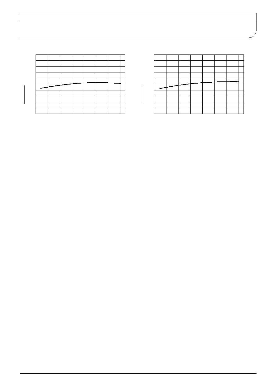
Junction Temp.
-
-
I
GT
-TjChange Rate
Typical
I
GT
t
I
GT
◊
100
Junction Temp.
.
.
.
.
.
.
.
.
.
-
-
V
GT
-TjTypical
Gate Trigger Voltage
V
SanRex 50 Seaview Blvd. Port Washington, NY 11050 PH(516)625-1313 FX(516)625-8845 E-mail:semi@sanrex.com