 | –≠–ª–µ–∫—Ç—Ä–æ–Ω–Ω—ã–π –∫–æ–º–ø–æ–Ω–µ–Ω—Ç: LA3375 | –°–∫–∞—á–∞—Ç—å:  PDF PDF  ZIP ZIP |

Any and all SANYO products described or contained herein do not have specifications that can handle
applications that require extremely high levels of reliability, such as life-support systems, aircraft's
control systems, or other applications whose failure can be reasonably expected to result in serious
physical and/or material damage. Consult with your SANYO representative nearest you before using
any SANYO products described or contained herein in such applications.
SANYO assumes no responsibility for equipment failures that result from using products at values that
exceed, even momentarily, rated values (such as maximum ratings, operating condition ranges,or other
parameters) listed in products specifications of any and all SANYO products described or contained
herein.
Monolithic Digital IC
Pilot Cancel-Provided PLL
FM MPX Demodulator for Car Stereos
Ordering number:ENN901E
LA3375
SANYO Electric Co.,Ltd. Semiconductor Company
TOKYO OFFICE Tokyo Bldg., 1-10, 1 Chome, Ueno, Taito-ku, TOKYO, 110-8534 JAPAN
10700TH (KT)/90196RM/D177KI/8044KI/5205KI/ No.901≠1/11
Package Dimensions
unit:mm
3193-SIP16Z
[LA3375]
SANYO : SIP16Z
Overview
The LA3375 integrates two functions : skip-noise preven-
tion and pilot cancelling. It is a multiplex, 16-pin IC for
FM car stereos.
Functions
∑ Pilot-cancelling (level-following).
∑ Stereo noise controlling (SNC).
∑ High-cut control (HCC).
∑ Stereo-monaural automated selection (with priorities for
pilot inputs).
∑ VCO oscillation damping.
Features
∑ Low distortion (0.05% typ., 300-mV input, mono.).
∑ Power supply ripple rejection (35 dB typ.).
∑ Wide operating voltage range (V
CC
=6.5 to 14V).
∑ Small due to single-ended package.
∑ 3 mm pitch-pin spacing makes it easy to use in printed
circuit boards.
Specifications
Absolute Maximum Ratings
at Ta = 25∞C
∞C
∞C
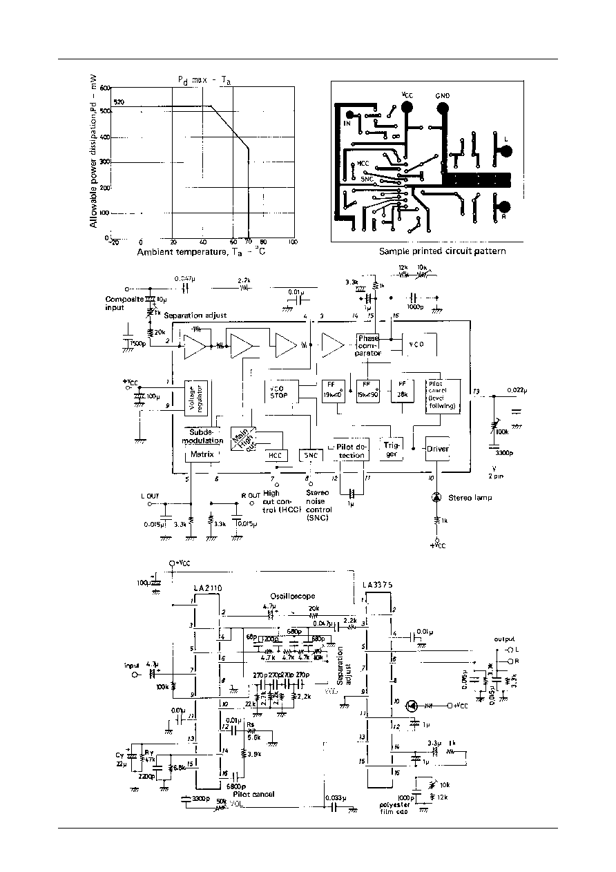
Recommended Operating Conditions
at Ta = 25∞C
Ta
45∞C
r
e
t
e
m
a
r
a
P
l
o
b
m
y
S
s
n
o
i
t
i
d
n
o
C
s
g
n
i
t
a
R
t
i
n
U
e
g
a
t
l
o
v
y
l
p
p
u
s
m
u
m
i
x
a
M
V C
C
x
a
m
6
1
V
t
n
e
r
r
u
c
g
n
i
v
i
r
d
p
m
a
L
IL
x
a
m
0
4
A
m
n
o
i
t
a
p
i
s
s
i
d
r
e
w
o
p
e
l
b
a
w
o
ll
A
Pd
x
a
m
0
2
5
W
m
e
r
u
t
a
r
e
p
m
e
t
g
n
i
t
a
r
e
p
O
T
r
p
o
0
7
+
o
t
0
2
≠
e
r
u
t
a
r
e
p
m
e
t
e
g
a
r
o
t
S
T g
t
s
5
2
1
+
o
t
0
4
≠
r
e
t
e
m
a
r
a
P
l
o
b
m
y
S
s
n
o
i
t
i
d
n
o
C
s
g
n
i
t
a
R
t
i
n
U
e
g
a
t
l
o
v
y
l
p
p
u
s
r
e
w
o
p
d
e
d
n
e
m
m
o
c
e
R
V C
C
4
1
o
t
5
.
6
V
e
g
a
t
l
o
v
l
a
n
g
i
s
t
u
p
m
I
vi
0
0
3
o
t
0
0
2
V
m
3.25
8.8max
6.5
3.6
2.2min
1.5
0.25
24.2
0.5
0.85
3.0
1
16
3.0
1.5

LA3375
No.901≠2/11
Operating Characteristics
at Ta = 25∞C, V
CC
=10V, v
i
=300mV, f=1kHz, L+R=90%, pilot=10%, Rg=20k
,
See specified Test Circuit.
Specified test circuit
Note : SW1 : A, SW2 : C unless otherwise specified.
r
e
t
e
m
a
r
a
P
l
o
b
m
y
S
s
n
o
i
t
i
d
n
o
C
s
g
n
i
t
a
R
t
i
n
U
n
i
m
p
y
t
x
a
m
t
n
e
r
r
u
c
t
n
e
c
s
e
i
u
Q
I
o
c
c
2
2
8
2
A
m
n
o
i
t
a
r
a
p
e
s
l
e
n
n
a
h
C
p
e
S
B
:
1
W
S
0
4
0
5
B
d
r
o
t
c
a
f
n
o
i
t
r
o
t
s
i
d
l
a
r
u
a
n
o
M
D
H
T
o
n
o
m
V
m
0
0
3
=
o
n
o
m
5
0
.
0
2
.
0
%
r
o
t
c
a
f
n
o
i
t
r
o
t
s
i
d
o
e
r
e
t
S
D
H
T
T
S
n
i
a
m
5
0
.
0
2
.
0
%
l
e
v
e
l
g
n
i
t
h
g
il
p
m
a
L
VL
%
0
1
=
t
o
li
p
,
%
0
9
=
R
+
L
0
6
5
8
0
2
1
V
m
s
i
s
e
r
e
t
s
y
H
hy
3
6
B
d
e
g
n
a
r
e
r
u
t
p
a
C
R
C
V
m
0
3
=
t
o
li
p
3
±
%
l
e
v
e
l
l
a
n
g
i
s
t
u
p
t
u
O
vo
b
u
s
0
5
1
5
1
2
0
0
3
V
m
o
i
t
a
r
N
/
S
N
/
S
k
0
2
=
g
R
8
6
4
7
B
d
k
0
1
=
g
R
0
7
8
7
B
d
)
3
n
i
p
(
e
c
n
a
t
s
i
s
e
r
t
u
p
n
I
ri
0
2
k
o
i
t
a
r
n
o
i
t
c
e
j
e
r
A
C
S
A
C
S
j
e
r
0
8
B
d
e
g
a
t
l
o
v
t
u
p
n
i
e
l
b
a
w
o
ll
A
vi
k
0
2
=
g
R
,
%
1
=
D
H
T
0
0
7
0
0
9
V
m
k
0
1
=
g
R
,
%
1
=
D
H
T
0
5
4
V
m
n
o
i
t
a
u
n
e
t
t
a
t
u
p
t
u
o
C
N
S
A tt
C
N
S
V8
%
0
1
=
t
o
li
p
,
%
0
9
=
R
≠
L
,
V
6
.
0
=
5
.
8
≠
0
.
3
≠
3
.
0
≠
B
d
e
g
a
t
l
o
v
t
u
p
t
u
o
C
N
S
vo
b
u
s
V8
%
0
1
=
t
o
li
p
,
%
0
9
=
R
≠
L
,
V
1
.
0
=
5
V
m
n
o
i
t
a
u
n
e
t
t
a
t
u
p
t
u
o
C
C
H
A tt
)
1
(
C
C
H
V7
%
0
1
=
t
o
li
p
,
%
0
9
=
R
+
L
,
V
6
.
0
=
0
.
5
1
≠
0
.
9
≠
5
.
0
≠
B
d
A tt
)
2
(
C
C
H
V7
%
0
1
=
t
o
li
p
,
%
0
9
=
R
+
L
,
V
1
=
0
.
2
≠
0
B
d
n
o
i
t
c
e
j
e
r
e
l
p
p
i
r
y
l
p
p
u
s
r
e
w
o
P
Rr
5
3
B
d
e
g
a
t
l
o
v
g
n
i
p
p
o
t
s
O
C
V
p
o
t
s
O
C
V
3
.
7
V
e
c
n
a
l
a
b
l
e
n
n
a
h
C
a
B
H
C
5
.
0
5
.
1
B
d
r
o
t
c
a
f
n
o
i
t
a
ll
e
c
n
a
c
t
o
li
P
L
C p
0
2
5
2
B
d
LA3375
No.901≠3/11
Sample application circuit 1
Sample application circuit 2 : sample circuit for LA2110 and LA3375

LA3375
No.901≠4/11
Cautions when employing sample application circuits
1) Adjust separation by 10k
potentiometer in low pass filter.
2) Adjust R
S
for noise detection sensitivity under strong to medium radio fields. Set at appropriate value.
3) Adjust noise AGC by C
Y
and R
Y
to enhance noise suppression in medium to weak radio fields.
4) Adjust pilot cancellation by 50k
potentiometer connected to pin 15 of LA2110.
5) Reponse speeds of pilot cancellation to follow levels can be varied by adjusting capacitance value of 1
µ
F capacitor
connected across pins 11 and 12 of LA3375. Distortion factors deteriorate with reduction in value.
6) Adjusting pilot cancellation.
For example consider the sample application circuit 2. Assume the input signal consists only of pilot signals. First
connect an oscilloscope and a valve voltmeter to pin 2 of the LA2110. Set their ranges for V : 200mV/div. AC, H :
20
µ
s/div.
When oscilloscope waveform is
turn pilot cancel control to change it to the following :
Then, adjust pilot cancel control to minimize indications of valve voltmeter.
When the LA3375 alone is used (sample application circuit 1), adjust cancel control through a 19kHz BPF to
minimize carrier leakage level at output pins (pins 5 and 6).
*Refer to the LA2110 catalog for LA3375/LA2110 applications and characteristics.
1. Pilot cancelling circuit
A level-following type has been used. Once set, it can easily accommodate varying pilot modulation depths among
stations. Cancelling signal is a sawtooth wave obtained by integrating a square wave that is proportionate in ampli-
tude to pilot level with C and R.
2. Separation adjustments
The LA3375 has separation parameters that have been set to provide maximum separation when used in conjunction
with the LA2210, a noise-canceler IC, or the equivalent. The LA3375 by itself exhibits separation only in a 25 to 30
dB range. If a phase correction circuit is provided in the LA3375 input circuit, it can exhibit intrinsic separation
charactersitics, typically 50 dB.
3. Adjusting the free running frequency
Use a timing set resistor and a semi-set resistor, when connecting a frequency counter. Connect the counter with a
high impedance input to the connection between these resistors with a 100-k
resistor, as shown below.

LA3375
No.901≠5/11
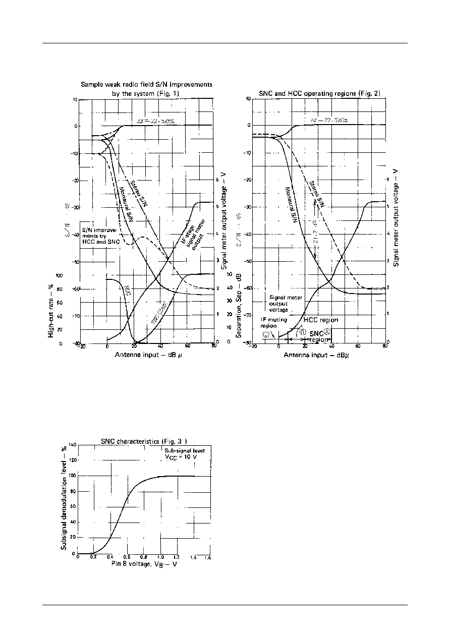
4. SNC (stereo noise control) and HCC (high-cut control)
The LA3375 has SNC and HCC terminals for improved S/N ratios when operating in weak radio fields. By adjusting
the SNC terminal, noises unique to stereo FM in weak fields can be reduced. The HCC terminals permits further
improvement of effective S/N ratios by lowering treble levels of FM noises in weak fields. (See Fig. 2)
STEREO deteriorates approximately 21.7 dB (compared to MONO) in weak radio feilds (Fig. 2). Generally, when
S/N ratios deteriorate below 30 to 40 dB, noises become quite noticeable. Section (1) shows ways to set SNC and
HCC when radio field strengths are divided into 3 regions, A, B, and C, (Fig. 2). SNC is expected to function in
region A, and HCC in region B. In region C, shallow muting is effected in the IF stage.
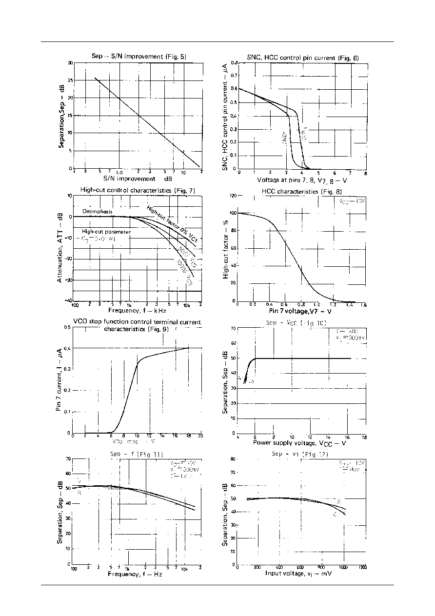
(1) SNC (stereo noise control)
Stereo S/N ratios deteriorate 21.7 dB below monaural but can be improved by varying stereo separation. S/N
improvement becomes apparent, however, only when the separation is 20 dB or worse. In that case, the relation
between separation and S/N improvement is shown in Fig. 5.
SNC in the LA3375 improves S/N ratios in weak radio fields by varying separation. It varies subsignal demodula-
tion level and controls separation. By using the IF stage signal meter level output as the source of the control
signal, S/N ratios in region A of Fig. 2 can be maintained at about 40 dB or better. Ideal S/N enhancements should
provide gradual switching over from stereo to monaural to maintain constant S/N ratios, starting from a point in
region A for 40-dB stereo S/N toward a point for 40-dB monaural S/N. Methods to set the control level will be
described later.
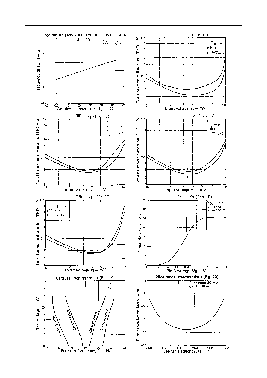
Fig. 3 shows voltages applied to pin 8 (SNC terminal) of the LA3375 versus separation characteristics (SNC
characteristics). Pin 8 is also the base of a PNP transistor, so stereo mode is set when pin 8 is open and monaural
mode is set when it is grounded. SNC terminal control is effective only when locked with pilot signals and when
stereo indicator is lit. External circuit parameters can be chosen in large values that do not affect the IF stage
meter output circuit because SNC control currents are small. This makes designing easy. (See Fig. 6)
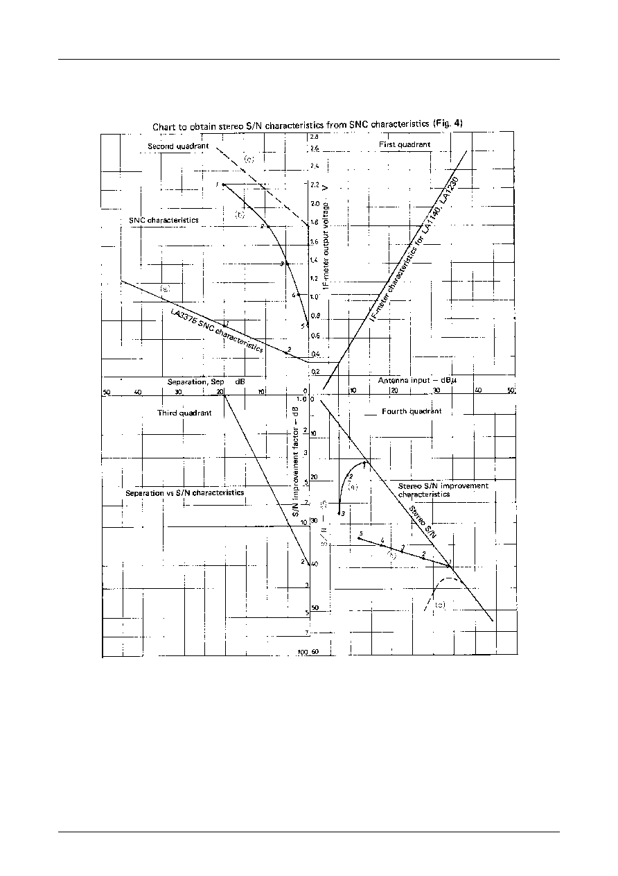
(2) Designing external circuits for SNC characteristics
We recommend the following as a way to designate SNC characteristics to have smooth transition of separation
from stereo to monaural in region A of Fig. 2.
Separation vs S/N-enhancement relation ....................................................... Refer to Fig. 5.
SNC terminal voltages vs separation characteristics ..................................... Refer to Fig. 3.
Antenna inputs vs S/N improvement characteristics can be obtained from the drawing if the graph for IF-stage
signal meter output vs antenna iuput and the graph for stereo S/N-ratio vs antenna input are known. From desired
S/N characteristics, SNC terminal voltage characteristics can also be obtained.
Sample drawings are shown in Fig. 4, where for simplicity's sake, SNC, IF meter, and stereo S/N characteristics
have been approximated with straight lines.
For instance :
To obtain stereo S/N improvement characteristics from SNC characteristics, when (a) in the second quadrant of
the chart represents bare SNC characteristics, point 1 projected to the third quadrant shows a 20 dB separation
and a 1 dB S/N improvement. When projected from the frist to the fourth quadrant, a point improved by 1 dB
in S/N over the stereo S/N line in the fourth quadrant corresponds to point 1.
Similarly, point 2 on the SNC characteristics in the second quadrant corresponds to point 2 in the fourth
quadrant. Point 3 in the second quadrant corresponds to point 3 in the fourth quadrant. Stereo S/N improve-
ment characteristics for each point are obtainable.
Similarly, (b) characteristics in the second quadrant are projected to form (b) characteristics in the fourth
quadrant, and (c) in the second quadrant to form (c) in the fourth quadrant, thus providing a way to diagram
improvement characteristics.
In the resulting drawings, ideal S/N improvement characteristics are similar to (b) in the fourth quadrant, but
corresponding SNC characteristics have to be (b) characteristics in the second quadrant which are difficult to
realize. Among realistic characteristics, something like (c) appears to be satisfactory. The (c) SNC characteristics
are obtained with a shift by two diodes together with a 1/2 bleeder.

LA3375
No.901≠6/11
(3) HCC (high-cut control)
In region B where S/N deteriorates to 40 dB or worse even for monaural, the S/N as sensed by the human ear can
be enhanced by suppressing levels at frequencies above approximately 7kHz.
Treble region levels that follow meter voltages can be smoothly attenuated (high-cut control) by impressing IF-
stage signal meter output to the HCC pin (pin 7) of the LA3375. Fig. 7 shows MPX output frequency characteris-
tics (monaural) provided by voltages impressed on pin 7. Frequency characteristics for a 100% high cut can be
designated by an external capacitor connected to pin 4. An equivalent circuit is shown below where the designa-
tion is made by the 5k
and the C time constant. Approximate values provided by C as expressed in attenuation
at 10kHz are listed in table below : right.
Fig. 8 shows the relation between noltages impressed on pin 7 and rates (%) of high cut (HCC). When IF meter
output voltage characteristics and region B, S/N characteristics, of Fig. 2 have been obtained, S/N improvement
by HCC can be drawn in a way similar to drawing SNC characteristics.
Fig. 2 shows typical meter outputs of a quadrature detection IF amplifier IC. (Fig. 1 shows data for the LA1140,
LA1230, and LA1231N) HCC characteristics have been designated to permit region B improvements when the IC
is directly connected to HCC (pin 7) terminal of the LA3375. The infinitesmal control currents at pin 7, similar to
pin 8, do not affect meter outputs.
(4) SNC and HCC connection circuits when coupled with the IF stage
Fig. 1 shows sample S/N characteristics vs antenna inputs when SNC and HCC are connected with the IF stage
by an external circuit.
(5) S/N improvements in region C of Fig. 1
Because S/N ratios deteriorate even further in the region C of Fig. 1, it is better to improve the S/N in this region
with IF mutings. The LA1140 is available to linearly vary the IF muting. Employment of the LA3375 together
with the LA1140 further enhances S/N improvement.
(6) Using the HCC terminal for muting
Mutings in the neighborhood of 37 dB are feasible by utilizing HCC functions as muting functions when used in
home stereos and no need exists to suppress treble noises. Fade-in and fade-out of mutings, permitting delightful,
shock-noise-free muting are possible by providing a time constant to the pin 7 control.
(7) VCO damping
VCO oscillations can be damped by applying a voltage not less than 7 V to the HCC terminal (pin 7) to induce a
monaural mode. At this time, both SNC and HCC are in an off mode. Fig. 9 shows flow-in current by voltages
applied to pin 7.
LA3375
No.901≠7/11
LA3375
No.901≠8/11
LA3375
No.901≠9/11
LA3375
No.901≠10/11
Specifications of any and all SANYO products described or contained herein stipulate the performance,
characteristics, and functions of the described products in the independent state, and are not guarantees
of the performance, characteristics, and functions of the described products as mounted in the customer's
products or equipment. To verify symptoms and states that cannot be evaluated in an independent device,
the customer should always evaluate and test devices mounted in the customer's products or equipment.
SANYO Electric Co., Ltd. strives to supply high-quality high-reliability products. However, any and all
semiconductor products fail with some probability. It is possible that these probabilistic failures could
give rise to accidents or events that could endanger human lives, that could give rise to smoke or fire,
or that could cause damage to other property. When designing equipment, adopt safety measures so
that these kinds of accidents or events cannot occur. Such measures include but are not limited to protective
circuits and error prevention circuits for safe design, redundant design, and structural design.
In the event that any or all SANYO products(including technical data,services) described or
contained herein are controlled under any of applicable local export control laws and regulations,
such products must not be expor ted without obtaining the expor t license from the author ities
concerned in accordance with the above law.
No part of this publication may be reproduced or transmitted in any form or by any means, electronic or
mechanical, including photocopying and recording, or any information storage or retrieval system,
or otherwise, without the prior written permission of SANYO Electric Co. , Ltd.
Any and all information described or contained herein are subject to change without notice due to
product/technology improvement, etc. When designing equipment, refer to the "Delivery Specification"
for the SANYO product that you intend to use.
Information (including circuit diagrams and circuit parameters) herein is for example only ; it is not
guaranteed for volume production. SANYO believes information herein is accurate and reliable, but
no guarantees are made or implied regarding its use or any infringements of intellectual property rights
or other rights of third parties.
This catalog provides information as of January, 2000. Specifications and information herein are subject
to change without notice.
LA3375
PS No.901≠11/11