61004 JO IM No.7874-1/3
LA6570
Overview
The LA6570 is a 5CH driver (BTL : 4CH, H-bridge : 1CH) for CD players.
Features
∑
Built-in POWER AMP 5CH (bridge connection (BTL) : 4CH, H-bridge : 1CH)
∑
IO max 1A
∑
Built-in level shift circuit (Except H-bridge.)
∑
Built-in MUTE circuit (output ON/OFF).
(Operates only for CH1 to CH4 BTL AMP. No operation for H-bridge and 5VREG.)
∑
Built-in 5V regulator (with external PNP transistor)
∑
Implements VREF switching function (Select H for external, or L for internal (2.5 V))
∑
Built-in overheat protection circuit (Thermal shutdown)
Specifications
Maximum Ratings
at Ta = 25
∞
C
Parameter Symbol
Conditions
Ratings
Unit
Power supply voltage
VCC max
14
V
Independent IC
0.8
Allowable operation
Pd max
Specific board *
2.0
W
Maximum output current
IO max
Each output of CH1 to CH4 and H-bridge
1
A
Maximum input voltage
VINB
13
V
MUTE pin voltage
VMUTE
13
V
Operating temperature
Topr
-30 to +85
∞
C
Storage temperature
Tstg
-55 to +150
∞
C
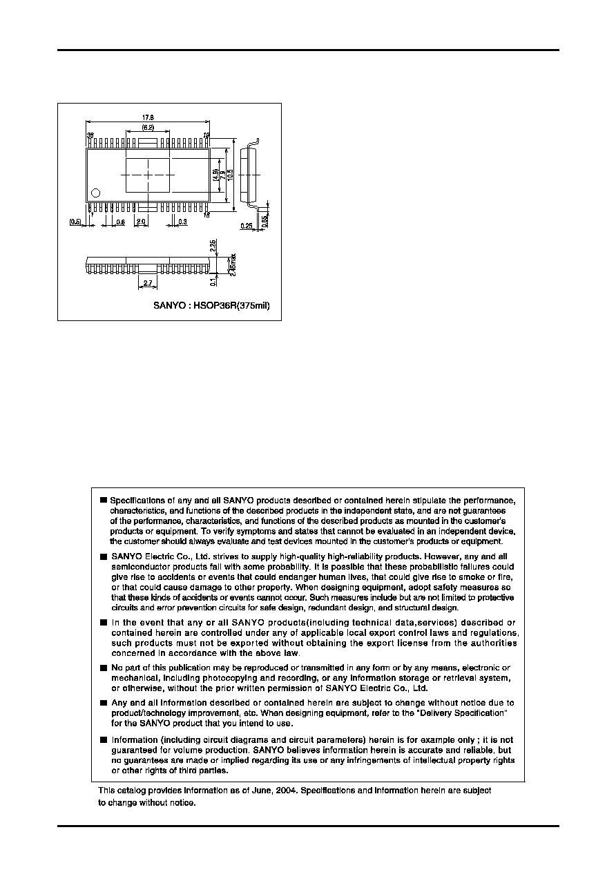
* Specific board size: 76.1 mm
◊
114.3 mm
◊
1.6 mm, board material: glass epoxy resin.
Recommended Operating Conditions
at Ta = 25
∞
C
Parameter Symbol
Conditions
Ratings
Unit
Power supply voltage
VCC
5.6
to
13
V
Ordering number : ENN*7874
Monolithic Linear IC
5CH Driver (BTL : 4CH, H-Bridge : 1CH) for CD
LA6570
No.7874-2/3
Electrical Characteristics
at Ta = 25
∞
C, VCC1 = VCC2 = 8V, VREF = 2.5V unless otherwise specified
Ratings
Parameter Symbol
Conditions
min typ max
Unit
[Whole]
No-load current consumption ON
ICC-ON
BLT AMP output ON, LODING block OFF *1
30 50
mA
No-load current consumption OFF
ICC-OFF
All output OFF *1
10 15
mA
Thermal shutdown operating temperature
TSD
Design guaranteed performance
150 175 200
∞
C
[VREF-AMP]
VREF-AMP offset voltage VREF-OFFSET
-10
10
mV
VREF input voltage range
VREF-IN
1
VCC-1.5
V
VREF-OUT output current
I-VREF-OUT
CH1 input reference voltage
2 5
mA
[BTL AMP block] (CH1 to CH4)
Output offset voltage
VOFF
Voltage differences between BTL AMP and
each channel output. *2
-50
50
mV
Input voltage range
VIN
Input voltage range of input OP-AMP
0
VCC-1.5
V
Output voltage
VO For
RL = 8
, between each VO+ and VO- *3
5.7 6.2
V
Closed circuit voltage gain
VG
Gain between input and output,
input OP-AMP:BUFFER
3.6 4
4.4
times
Slew rate
SR
For output by AMP alone, it must be doubled
0.5
V/
µ
s
MUTE ON voltage
VMUTE-ON
Output ON voltage, each MUTE *4
2
V
MUTE OFF voltage
VMUTE-OFF
Output OFF voltage, each MUTE *4
0.5
V
[Input AMP block] (CH1 to CH4)
Input voltage range
VIN-OP
0
VCC-1.5
V
Output current (SINK)
SINK-OP
2
mA
Output current (SOURCE)
SOURCE-OP
*5
300 500
µ
A
Output offset voltage
VOFF-OP
-10
10
mV
CH1 input switching voltage 1
VSW-OP1
CH1 input AMP (B), external VREF selected *6
2
V
CH1 input switching voltage 2
VSW-OP2
CH1 input AMP (A), Internal VREF selected *6
0.5
V
[Loading block] (CH5, H-bridge)
Output voltage
VO-LOAD
Between outputs for Normal/Reverse rotation,
RL = 8
5.7 6.5
V
Brake output saturation voltage
VCE-BREAK
For brake, output voltage *8
0.3
V
Input "L" level
VIN-L
1
V
Input "H" level
VIN-H
2
V
[Power supply block] (with external PNP transistor : 2SB632K is used)
5V power supply output
VOUT
IO=200mA
4.8 5.0 5.2
V
REG-IN SINK current
REG-IN-SINK
Base current of external PNP transistor *9
5 10
mA
Line regulation
VOLN 6V
VCC
12V, IO=200mA
10 100
mV
Load regulation
VOLD 5mA
IO
200mA
10 100
mV
*1. Total current consumption of VCC1 and VCC2 when non-load.
*2. Input AMP is BUFFER AMP.
*3. Voltage differences between both ends of load (8
). Output is saturated.
*4. When MUTE is "H", output is ON. When MUTE is "L", output is OFF (HI impedance).
*5. Input OP-AMP SOURCE is constant current. Since 11k
resistance to the next level is loaded,
special care should be taken for the gain setting of input OP-AMP.
*6. When VIN1-SW is "L", select AMP-A for input AMP and internal VREF (nearly equal to 2.5V) for VREF.
When VIN-SW is "H", select AMP-B for input AMP and external VREF (nearly equal to VREF-IN) for VREF.
*7. Voltage of upper side (SOURCE) and lower side (SINK). For Normal/Reverse rotation. Output voltage is obtained
by subtracting this value from VCC.
*8. Brake is short (GND) brake. Output of SINK side is ON.
*9. 5VREG has built-in dropping protection circuit. Operates when base current is 10mA (TYP).