 | –≠–ª–µ–∫—Ç—Ä–æ–Ω–Ω—ã–π –∫–æ–º–ø–æ–Ω–µ–Ω—Ç: LB1948M | –°–∫–∞—á–∞—Ç—å:  PDF PDF  ZIP ZIP |
SANYO Electric Co.,Ltd. Semiconductor Company
TOKYO OFFICE Tokyo Bldg., 1-10, 1 Chome, Ueno, Taito-ku, TOKYO, 110-8534 JAPAN
Ordering number : ENN7714
31004TN (OT) No. 7714-1/6
Overview
The LB1948M is a two-channel low saturation voltage forward/reverse motor driver IC. It is optimal for motor drive in
12V system products and can drive either two DC motors, one DC motor using parallel connection, or a two-phase
bipolar stepping motor with 1-2 phase excitation mode drive.
Applications
12V low saturation voltage forward/reverse motor drive
Features
∑ Supports 12V power supply systems
∑ Low saturation voltage: V
O
(sat)=0.5V (typical) at I
O
=400mA
∑ Zero current drawn in standby mode
∑ Braking function
∑ Supports parallel connection: I
O
max=1.6A, V
O
(sat)=0.6V (typical) at I
O
= 800mA
∑ Built-in spark killer diode
∑ Thermal shutdown circuit
∑ Miniature package: MFP-10S (6.5
◊
5.1mm)
Specifications
Absolute Maximum Ratings
at Ta=25∞C
SANYO Semiconductors
DATA SHEET
LB1948M
Monolithic Digital IC
Low saturation voltage drive
forward/reverse 12 V motor driver
2004.2.4
Parameter
Symbol
Conditions
Ratings
Unit
Maximum supply voltage
V
CC
max
≠0.3 to +20
V
Output voltage
V
OUT
≠0.3 to +20
V
Input voltage
V
IN
≠0.3 to +18
V
Ground pin source current
I
GND
Per channel
800
mA
Allowable power dissipation
Pd max1
Independent IC
350
mW
Pd max2
Mounted on a circuit board
*
870
mW
Operating temperature
Topr
≠20 to +85
∞C
Storage temperature
Tstg
≠40 to +150
∞C
Any and all SANYO products described or contained herein do not have specifications that can handle
applications that require extremely high levels of reliability, such as life-support systems, aircraft's
control systems, or other applications whose failure can be reasonably expected to result in serious
physical and/or material damage. Consult with your SANYO representative nearest you before using
any SANYO products described or contained herein in such applications.
SANYO assumes no responsibility for equipment failures that result from using products at values that
exceed, even momentarily, rated values (such as maximum ratings, operating condition ranges, or other
parameters) listed in products specifications of any and all SANYO products described or contained
herein.
*
: On the stipulated circuit board (114.3
◊
76.1
◊
1.6tmm, glass epoxy)
No.7714-2/6
LB1948M
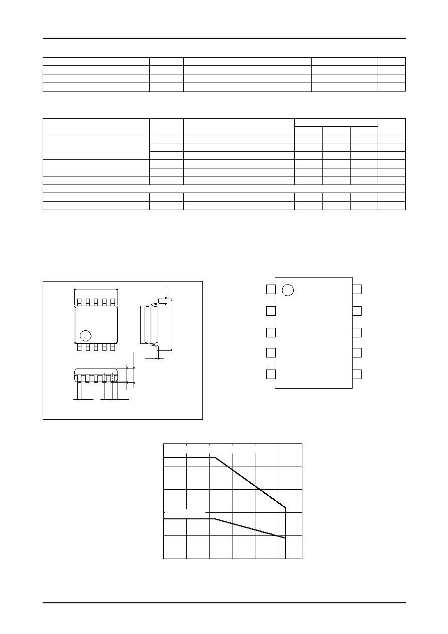
1
10
5
6
(0.5)
1.7max
1.0
0.35
5.0
0.15
6.4
(1.5)
0.1
4.4
0.63
VCC
1
IN1
2
LB1948M
Top view
ILB01591
IN2
3
IN3
4
IN4
5
OUT1
10
OUT2
9
OUT3
8
OUT4
7
GND
6
Parameter
Symbol
Conditions
Ratings
Unit
min
typ
max
I
CC
0
IN1, 2, 3, 4=0V (Standby mode)
0.1
10
µA
Current drain
I
CC
1
*
1 (Forward or reverse mode)
15
21
mA
I
CC
2
*
2 (Brake mode)
30
40
mA
Output saturation voltage
V
O (sat)
1
I
OUT
=200mA (High Side and Low Side)
--
0.25
0.35
V
V
O (sat)
2
I
OUT
=400mA (High Side and Low Side)
--
0.50
0.75
V
Input current
I
IN
V
IN
=5V
85
110
µA
[Spark Killer Diode]
Reverse current
IS (leak)
30
µA
Forward voltage
V
SF
I
OUT
=400mA
1.7
V
Electrical Characteristics
at Ta=25∞C, V
CC
=12V
Allowable Operating Ranges
at Ta=25∞C
Package Dimensions
Pin Assignment
unit : mm
3086B
SANYO : MFP10S (225 mil)
Parameter
Symbol
Conditions
Ratings
Unit
Supply voltage
V
CC
2.5 to 16
V
Input high-level voltage
V
IH
1.8 to 10
V
Input low-level voltage
V
IL
≠0.3 to +0.7
V
*
1: IN1/IN2/IN3/IN4=H/L/L/L or L/H/L/L or L/L/H/L or L/L/L/H
*
2: IN1/IN2/IN3/IN4=H/H/L/L or L/L/H/H
ILB01585
0
1.0
0.8
0.87
0.6
0.4
0.35
0.2
0.18
0.45
80
60
100
0
≠20
20
40
Pd max -- Ta
Allowable power dissipation, Pd max
--
W
Ambient temperature, Ta--
∞
C
Independent IC
Mounted on a 114.3
◊
76.1
◊
1.6tmm glass epoxy circuit board
No.7714-3/6
LB1948M
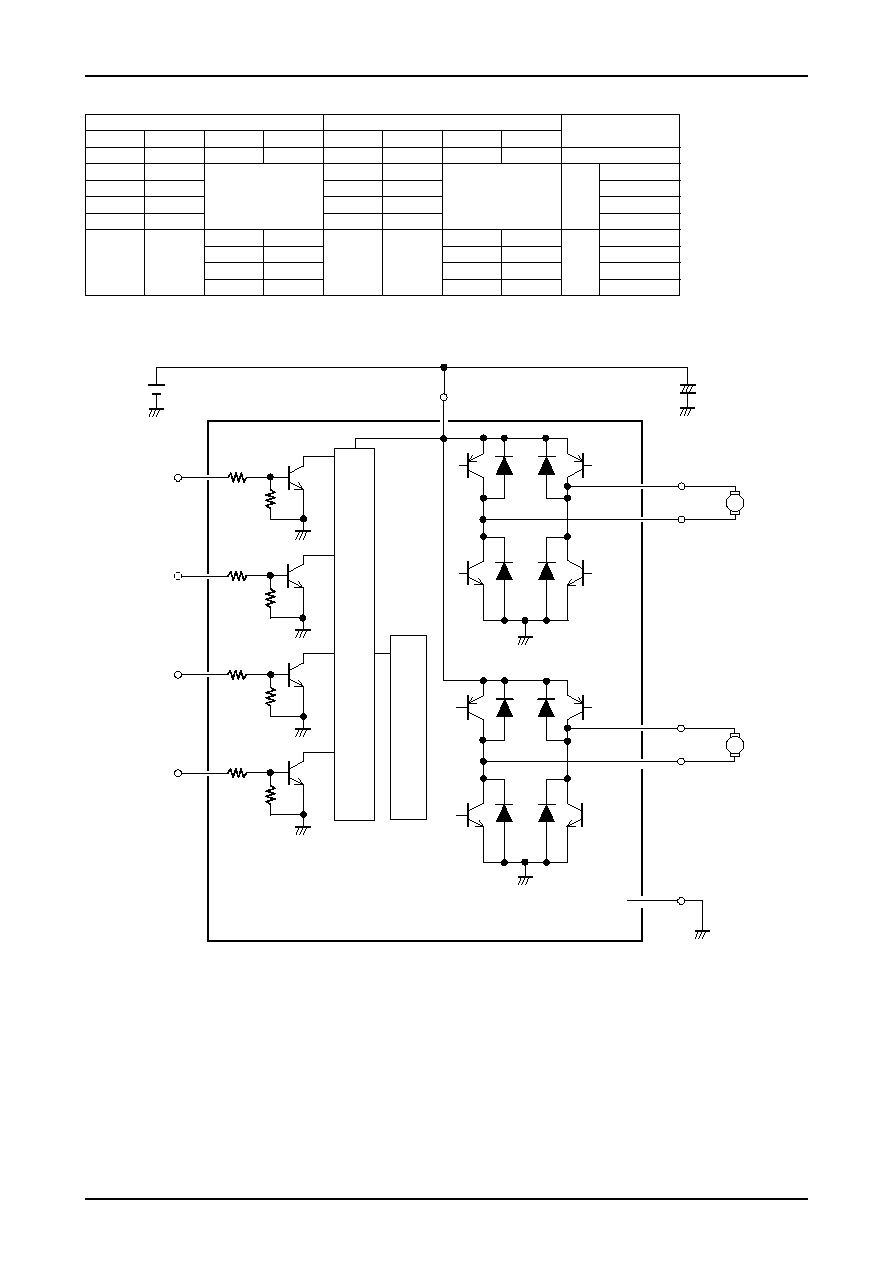
Block Diagram
IN1
IN2
IN3
IN4
60k
Control b
loc
k
Ther
mal shutdo
wn circuit
80k
60k
80k
60k
80k
60k
VCC
10
µ
F
OUT1
M
M
OUT2
OUT3
OUT4
GND
80k
Input
Output
Notes
IN1
IN2
IN3
IN4
OUT1
OUT2
OUT3
OUT4
L
L
L
L
OFF
OFF
OFF
OFF
Standby mode
L
L
OFF
OFF
1CH
Standby mode
H
L
H
L
Forward
L
H
L
H
Reverse
H
H
L
L
Brake
L
L
OFF
OFF
2CH
Standby mode
H
L
H
L
Forward
L
H
L
H
Reverse
H
H
L
L
Brake
Truth Table
No.7714-4/6
LB1948M
Design Documentation
∑ Voltage magnitude relationship
There are no restrictions on the magnitude relationships between the voltages applied to V
CC
and IN1 to IN4.
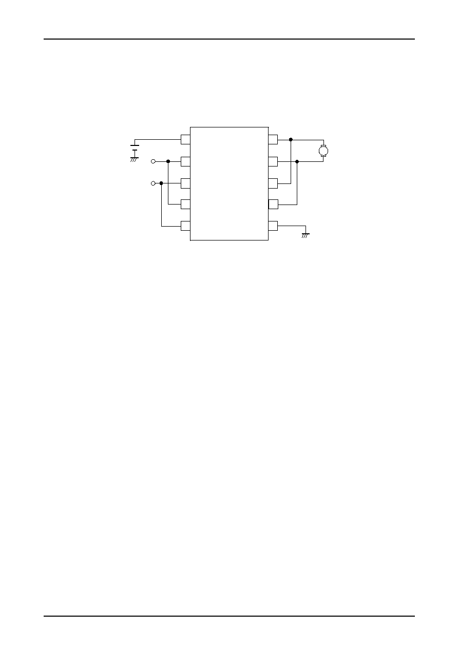
∑ Parallel connection
The LB1948M can be used as a single-channel H-bridge power supply by connecting IN1 to IN3, IN2 to IN4, OUT1
to OUT3, and OUT2 to OUT4 as shown in the figure. (I
O
max=1.6A, V
O
(sat)=0.6V (typical) at I
O
=800mA)
∑ Observe the following points when designing the printed circuit board pattern layout.
-- Make the V
CC
and ground lines as wide and as short as possible to lower the wiring inductance.
-- Insert bypass capacitors between V
CC
and ground mounted as close as possible to the IC.
-- Resistors of about 10K
must be inserted between the CPU output ports and the IN1 to IN4 pins if the
microcontroller and the LB1948M are mounted on different printed circuit boards and the ground potentials differ
significantly.
1 VCC
10
M
OUT1
2 IN1
9
OUT2
3 IN2
8
OUT3
4 IN3
7
OUT4
5 IN4
6
GND
No.7714-5/6
LB1948M
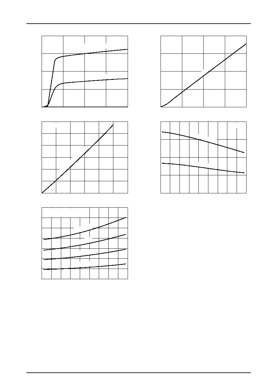
Supply voltage, VCC -- V
ICC -- VCC
Current drain, I
CC
--
mA
ILB01586
(=IN1 / IN2 or IN3 / IN4)
H / H
L / L
H / L, L / H
H / L, L / H
VIN=5V
Output current, IO -- mA
VO(sat) -- IO
Output saturation v
oltage,
V
O
(sat)
--
V
Output saturation v
oltage,
V
O
(sat)
--
V
0
10
20
40
30
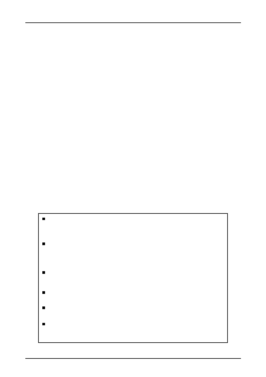
Ambient temperature, Ta --
∞
C
ICC -- Ta
Current drain, I
CC
--
mA
ILB01589
0
0
20
10
40
30
5
10
20
15
0
0
200
100
400
300
5
10
20
15
Input voltage, VIN -- V
IIN -- VIN
Input current, I
IN
--
µ
A
ILB01587
VCC=12V
--40
0
0.1
0.2
0.3
0.4
0.5
0.7
0.6
0
40
80
120
--20
20
60
100
140
Ambient temperature, Ta --
∞
C
VO(sat) -- Ta
ILB01590
VCC=12V
High Side and Low Side
IO=400mA
IO=300mA
IO=200mA
IO=100mA
--40
0
40
80
120
--20
20
60
100
140
VCC=12V
IN1 to 4
ILB01588
VCC=12V
High Side and Lo
w Side
0
0
0.3
0.4
0.1
0.2
0.5
0.6
200
400
100
300
600
500
(IN1 / 2) H / H
PS No.7714-6/6
LB1948M
Specifications of any and all SANYO products described or contained herein stipulate the performance,
characteristics, and functions of the described products in the independent state, and are not guarantees
of the performance, characteristics, and functions of the described products as mounted in the customer's
products or equipment. To verify symptoms and states that cannot be evaluated in an independent device,
the customer should always evaluate and test devices mounted in the customer's products or equipment.
SANYO Electric Co., Ltd. strives to supply high-quality high-reliability products. However, any and all
semiconductor products fail with some probability. It is possible that these probabilistic failures could
give rise to accidents or events that could endanger human lives, that could give rise to smoke or fire,
or that could cause damage to other property. When designing equipment, adopt safety measures so
that these kinds of accidents or events cannot occur. Such measures include but are not limited to protective
circuits and error prevention circuits for safe design, redundant design, and structural design.
In the event that any or all SANYO products(including technical data,services) d escribed or
contained herein are controlled under any of applicable local export control laws and regulations,
such products must not be expor ted without obtaining the expor t license from the author ities
concerned in accordance with the above law.
No part of this publication may be reproduced or transmitted in any form or by any means, electronic or
mechanical, including photocopying and recording, or any information storage or retrieval system,
or otherwise, without the prior written permission of SANYO Electric Co. , Ltd.
Any and all information described or contained herein are subject to change without notice due to
product/technology improvement, etc. When designing equipment, refer to the "Delivery Specification"
for the SANYO product that you intend to use.
Information (including circuit diagrams and circuit parameters) herein is for example only ; it is not
guaranteed for volume production. SANYO believes information herein is accurate and reliable, but
no guarantees are made or implied regarding its use or any infringements of intellectual property rights
or other rights of third parties.
This catalog provides information as of March, 2004. Specifications and information herein are subject to
change without notice.