Overview
The LC78856M and LC78856V are
-type digital-audio
D/A converter circuits with built-in digital filters.
Features
∑ 8
◊
oversampling digital filter
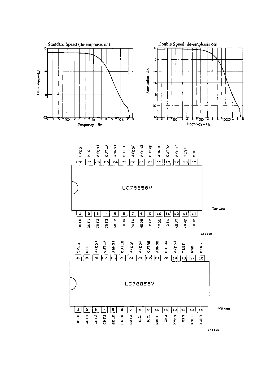
∑ Digital de-emphasis (supports fs = 44.1 kHz)
∑ Soft muting
∑ Double speed support
∑ Support for a 384fs system clock
∑ PWM outputs
∑ 5 V single-voltage power supply
∑ Si-gate CMOS process
Package Dimensions
unit: mm
3091A-MFP28
unit: mm
3191-SSOP30
CMOS LSI
53096HA (OT)/62095HA (OT) No. 5128-1/8
Preliminaly
SANYO: MFP28
[LC78856M]
SANYO: SSOP30
[LC78856V]
SANYO Electric Co.,Ltd. Semiconductor Bussiness Headquarters
TOKYO OFFICE Tokyo Bldg., 1-10, 1 Chome, Ueno, Taito-ku, TOKYO, 110 JAPAN
Built-in Digital Filter D/A Converters
for Digital Audio
LC78856M, 78856V
Ordering number : EN
*
5128A
Parameter
Symbol
Conditions
Ratings
Unit
Maximum supply voltage
V
DD
max
≠0.3 to +7.0
V
Maximum input voltage
V
IN
max
≠0.3 to V
DD
+ 0.3
V
Maximum output voltage
V
OUT
max
≠0.3 to V
DD
+ 0.3
V
Operating temperature
Topr
≠30 to +75
∞C
Storage temperature
Tstg
≠40 to +125
∞C
Specifications
Absolute Maximum Ratings
at Ta = 25∞C

No. 5128-2/8
LC78856M, 78856V
Parameter
Symbol
Conditions
Ratings
Unit
min
typ
max
Supply voltage
V
DD
3.0
5.5
V
Input voltage
V
IN
0
V
DD
V
Allowable Operating Ranges
at Ta = ≠30 to +75∞C
Parameter
Symbol
Conditions
Ratings
Unit
min
typ
max
Input high-level voltage (1)
V
IH
1
The XIN pin
0.7 V
DD
V
Input low-level voltage (1)
V
IL
1
The XIN pin
0.3 V
DD
V
Input high-level voltage (2)
V
IH
2
Pins other than the XIN pin
2.2
V
Input low-level voltage (2)
V
IL
2
Pins other than the XIN pin
0.8
V
Output high-level voltage
V
OH
I
OH
= ≠1 µA
V
DD
≠ 0.1
V
Output low-level voltage
V
OL
I
OL
= 1 µA
0.1
V
Power dissipation
Pd
V
DD
= 5.0 V
140
200
mW
DC Characteristics
at Ta = ≠30 to +75∞C, V
DD
= 4.5 to 5.5 V, V
SS
= 0 V
Parameter
Symbol
Conditions
Ratings
Unit
min
typ
max
Oscillator frequency
f
X
16.9
18.5
MHz
BCLK frequency
f
BCX
2.4
MHz
BCLK pulse width
t
WB
100
ns
Data setup time
t
DS
20
ns
Data hold time
t
DH
20
ns
LRCK setup time
t
LS
50
ns
LRCK hold time
t
LH
50
ns
DC Characteristics
at Ta = ≠30 to +75∞C, V
DD
= 4.5 to 5.5 V, V
SS
= 0 V
Timing Chart
Parameter
Symbol
Conditions
Ratings
Unit
min
typ
max
Total harmonic distortion
THD + N
f = 1 kHz, 0 dB
0.005
%
Signal-to-noise ratio
S/N
JIS-A
100
dB
Crosstalk
CT
f = 1 kHz, 0 dB
98
dB
Dynamic range
DR
JIS-A
94
dB
Analog Characteristics
at Ta = 25∞C, V
DD
= 5.0 V
No. 5128-5/8
LC78856M, 78856V
Pin Functions
SSOP
MFP
Symbol
Function
1
1
RSTB
Reset input (A low-level input resets the LSI internal circuits.)
2
2
CNT1
Emphasis on/off switching input
3
3
CNT2
Standard speed/double speed switching input
4
4
CNT3
Soft mute input
5
5
BCLK
Bit clock input
6
6
LRCK
LR clock input
7
7
DATA
Digital audio data input
10
8
MODE
Input format setting
11
9
CKO
Clock output
12
10
XV
DD
Oscillator amplifier power supply
13
11
XIN
Oscillator amplifier input
14
12
XOUT
Oscillator amplifier output
15
13
XGND
Oscillator amplifier ground
16
14
DGND
Digital system ground
17
15
MRO
Right channel mute signal output
18
16
TEST
Test pin (Must be tied low in normal operation.)
19
17
AV
DD
4
Analog system power supply
20
18
OUTRA
Right channel output A
21
19
AGND2
Analog system ground
22
20
OUTRB
Right channel output B
23
21
AV
DD
3
Analog system power supply
24
22
AV
DD
2
Analog system power supply
25
23
OUTLB
Left channel output B
26
24
AGND1
Analog system ground
27
25
OUTLA
Left channel output A
28
26
AV
DD
1
Analog system power supply
29
27
MLO
Left channel mute signal output
30
28
DV
DD
Digital system power supply
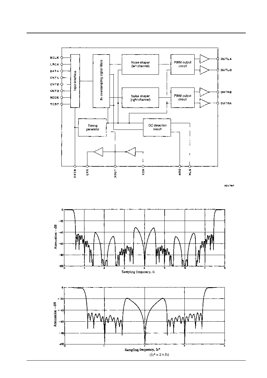
Operating Description
The LC78856M and LC78856V internal circuits can be roughly divided into the digital filter block and the 1-bit D/A
converter block.
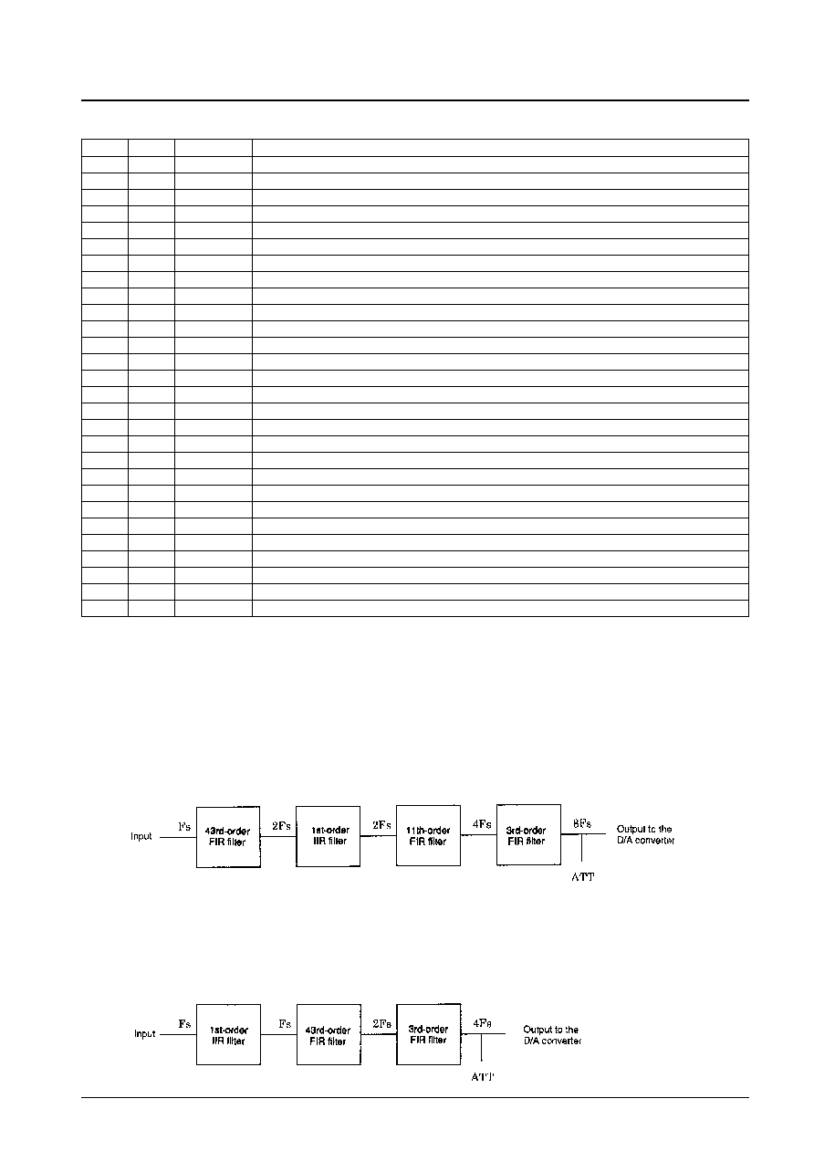
[Digital Filter Block]
1. Standard Speed
The LC78856M and LC78856V implements 8
◊
oversampling using three FIR filters: a 43rd-order filter, an 11th-
order filter, and a 3rd-order filter. A 1st-order IIR filter is used for de-emphasis.
2. Double Speed
Double-speed playback is used, for example, for dubbing CDs to audio tape at double speed. Here, the same
frequency is used for XIN, but BCLK, LRCK and DATA are input at twice the rates used in standard-speed
playback. After de-emphasis is applied with a 1st-order IIR filter, the signal is 4
◊
oversampled using a 43rd-order
FIR filter and a 3rd-order FIR filter.