STK311-110
SANYO Electric Co., Ltd. Semiconductor Business Headquarters
TOKYO OFFICE Tokyo Bldg., 1-10, 1 Chome, Ueno, Taito-ku, TOKYO, 110 JAPAN
60597HA (ID) / 32495TH (ID) No. 4588--1/5
Ordering number: EN 4588A
Thick Film Hybrid IC
RDS Demodulator
Overview
The STK311-110 is an RDS demodulator hybrid IC for
the Radio Data System (RDS), or multiplexed FM broad-
casting of various kinds of data, introduced within the
European Broadcasting Union (EBU). It demodulates the
multiplexed data modulating signal to recover the RDS
signal. In combination with an LC7070 series LSI (for
sync handling, error detection and correction), a low-cost
high-performance RDS data decode system can be con-
structed. Further, low-profile packaging is realized using
Sanyo's insulated metal substrate technology (IMST) for
the base, SC system and photoresist technologies and
folded board construction.
Applications
∑ Car stereos
∑ Home stereos
Features
∑ 57kHz BPF built-in for adjustment-free operation
∑ Few external components required for a complete RDS
data demodulation system
∑ ARI-SK/DK decoder built-in
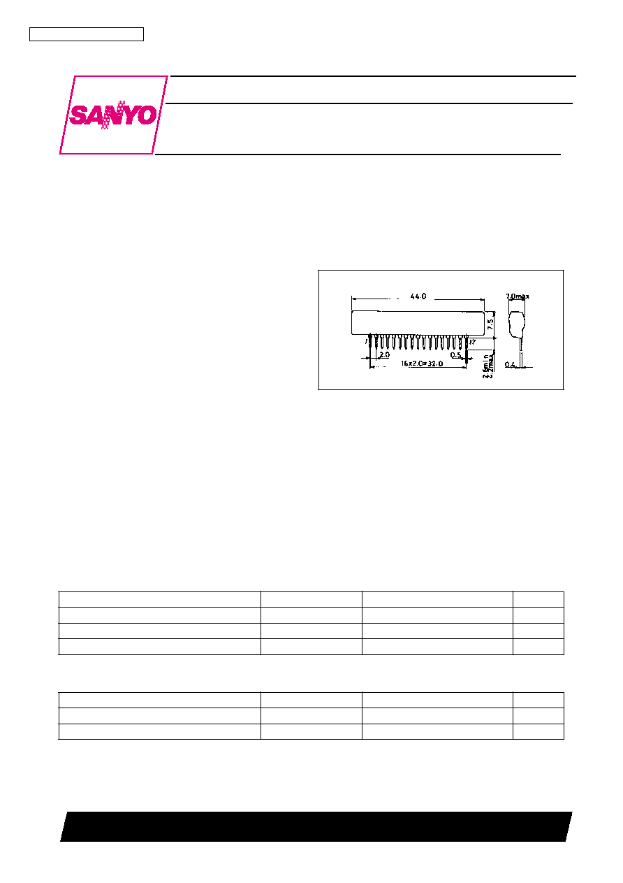
Package Dimensions
unit: mm
4142
[STK311-110]
Specifications
Maximum Ratings
at Ta = 25
∞
C
Recommended Operating Voltages
at Ta = 25
∞
C
Parameter
Symbol
Ratings
Unit
Maximum supply voltage
V
CC
max
6.3
V
Operating temperature
Topr
-
30 to +85
∞
C
Storage temperature
Tstg
-
40 to +100
∞
C
Parameter
Symbol
Ratings
Unit
Supply voltage
V
CC
5
V
Operating supply voltage range
V
CCOP
4.7 to 5.5
V
STK311-110
No. 4588--2/5
Operating Characteristics
at Ta = 25
∞
C, V
CC
= 5V
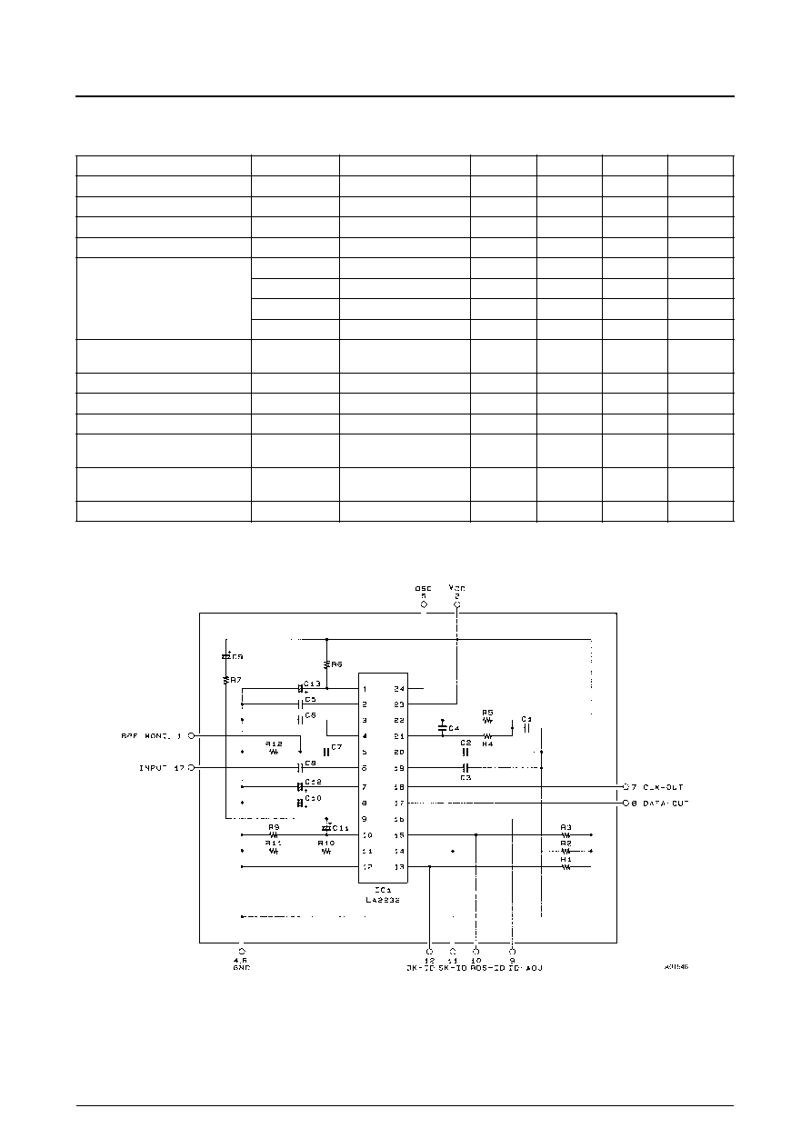
Equivalent Circuit
Parameter
Symbol
Conditions
min
typ
max
Unit
Quiescent current
I
CCO
≠
22
30
mA
Band-pass filter gain
VG
BPF
f = 57kHz
9
12.5
17
dB
Center frequency
55.8
57
58.2
kHz
Q
≠
9
≠
Band-pass filter selectivity
f = 90kHz (57kHz = 0dB)
-
50
-
38
-
20
dB
f = 60kHz (57kHz = 0dB)
-
4
-
2.5
0
dB
f = 54kHz (57kHz = 0dB)
-
5
-
3.5
0
dB
f = 38kHz (57kHz = 0dB)
-
50
-
39
-
35
dB
PLL capture range
CR
5mVrms, CW input
≠
-
0.5
+1.1
≠
%
RDS detector sensitivity
Pin 10 low, input on pin 17
0.15
0.4
1.0
mVrms
SK detector sensitivity
Pin 11 low, input on pin 17
0.3
1.0
2.0
mVrms
DK detector sensitivity
Pin 12 low, input on pin 17
0.8
1.5
2.6
mVrms
RDS input dynamic range
Pin 10 low, (ARI + RDS) signal
maximum input on pin 17
30
50
≠
mVrms
DK input dynamic range
Pin 12 low, ARI signal
maximum input on pin 17
75
100
≠
mVrms
VCO free-running frequency
f
OSC
453
456
459
kHz
R11 is a function trimming resistor.
Pins 3, 13 to 16 are no connection pins.
STK311-110
No. 4588--3/5
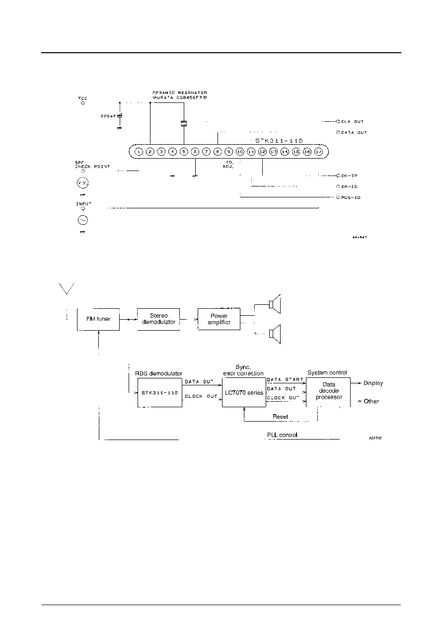
Sample Application Circuit
Sample System Configuration
Pins 3, 13 to 15 are left open.
STK311-110
No. 4588--4/5
Pin Functions
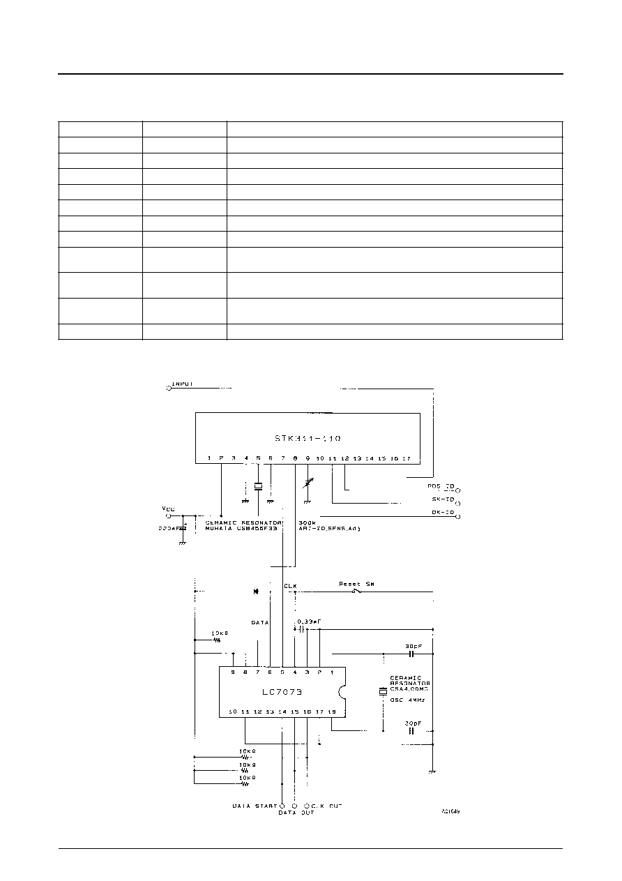
Sample RDS Data Decoder Circuit
Number
Name
Function
1
MONI
BPF (for adjustment) monitor output
2
V
CC
Supply pin
4, 6
GND
Ground pins
5
OSC
VCO ceramic oscillator pin (456kHz)
7
CLK OUT
Clock output
8
DATA OUT
Data output
9
ID-ADJ
SK detector sensitivity adjustment pin
10
RDS-ID
RDS signal detector indicator output.
Low-level output when an RDS signal is detected, and high-level when not detected.
11
SK-ID
SK signal detector indicator output.
Low-level output when an SK signal is detected, and high-level when not detected.
12
DK-ID
DK signal detector indicator output.
Low-level output when an DK signal is detected, and high-level when not detected.
17
INPUT
Input pin
STK311-110
No. 4588--5/5
s
No products described or contained herein are intended for use in surgical implants, life-support systems, aerospace equipment, nuclear
power control systems, vehicles, disaster/crime-prevention equipment and the like, the failure of which may directly or indirectly cause injury,
death or property loss.
s
Anyone purchasing any products described or contained herein for an above-mentioned use shall:
Accept full responsibility and indemnify and defend SANYO ELECTRIC CO., LTD., its affiliates, subsidiaries and distributors and all their
officers and employees, jointly and severally, against any and all claims and litigation and all damages, cost and expenses associated
with such use:
Not impose any responsibility for any fault or negligence which may be cited in any such claim or litigation on SANYO ELECTRIC CO.,
LTD., its affiliates, subsidiaries and distributors or any of their officers and employees, jointly or severally.
s
Information (including circuit diagrams and circuit parameters) herein is for example only; it is not guaranteed for volume production. SANYO
believes information herein is accurate and reliable, but no guarantees are made or implied regarding its use or any infringements of
intellectual property rights or other rights of third parties.
This catalog provides information as of June, 1997. Specifications and information herein are subject to change without notice.
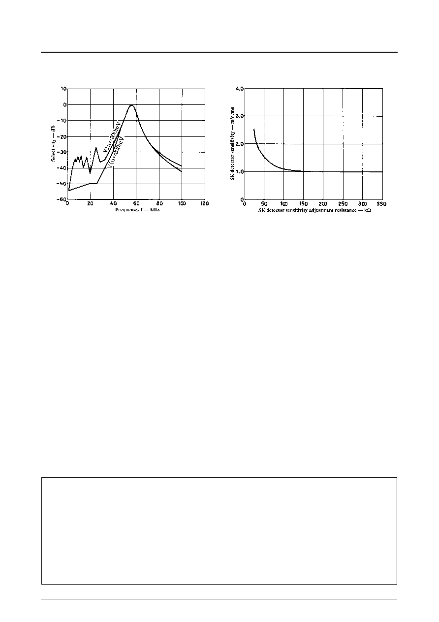
Characteristics Data
57kHz BPF selectivity
SK detector sensitivity adjustment