© by SEMIKRON
000111
1
I
:\M
A
R
K
E
T
IN
\F
R
A
ME
D
A
T\
dat
bl
\B
17
-S
em
i
t
op
\sk8
gh0
62.
fm
Absolute Maximum Ratings
Symbol Conditions
1)
Values
Units
V
CES
V
GES
I
C
I
CM
I
F
= ≠I
C
I
FM
= ≠I
CM
T
h
= 25/80 ∞C
t
p
< 1 ms; T
h
= 25/80 ∞C
T
h
= 25/80 ∞C
t
p
< 1 ms; T
h
= 25/80 ∞C
600
± 20
11 / 8
22 / 16
20 / 15
40 / 30
V
V
A
A
A
A
T
j
T
stg
T
sol
V
isol
Terminals, 10 s
AC, 1 min
≠ 40 ... + 150
≠ 40 ... + 125
260
2500
∞C
∞C
∞C
V
Characteristics
Symbol Conditions
1)
min.
typ.
max.
Units
V
CEsat
t
d(on)
t
r
t
d(off)
t
f
E
on
+ E
off
C
ies
R
thjh
3)
I
C
= 5 A; T
j
= 25 (125) ∞C
V
CC
= 300 V; V
GE
= + 15 V
I
C
= 5 A, T
j
= 125 ∞C
R
Gon
= R
Goff
= 200
inductive load
V
CE
= 25 V; V
GE
= 0V, 1 MHz
per IGBT
≠
≠
≠
≠
≠
≠
≠
≠
2,1(2,2)
68
42
470
75
0,53
0,29
≠
2,7(2,8)
≠
≠
≠
≠
≠
≠
3,0
V
ns
ns
ns
ns
mJ
nF
K/W
Inverse Diode
2)
V
F
= V
EC
V
TO
r
T
I
RRM
Q
rr
E
off
R
thjh
3)
I
F
= 5 A; T
j
= 25 (125) ∞C
T
j
= 125 ∞C
T
j
= 125 ∞C
I
F
= 5 A; V
R
= 300 V
di
F
/dt = ≠ 200 A/
µ
s
V
GE
= 0 V; T
j
= 125 ∞C
per Diode
≠
≠
≠
≠
≠
≠
≠
1,25(1,13)
0,85
55
5,3
0,61
0,06
≠
1,3(1,3)
0,9
80
≠
≠
≠
2,7
V
V
m
A
µ
C
mJ
K/W
Mechanical Data
M
1
w
mounting torque
≠
≠
≠
21
2,0
≠
Nm
g
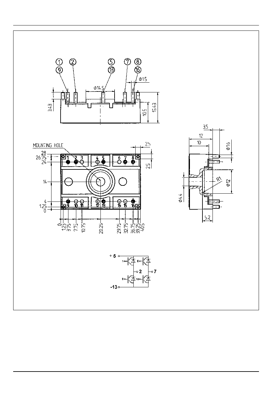
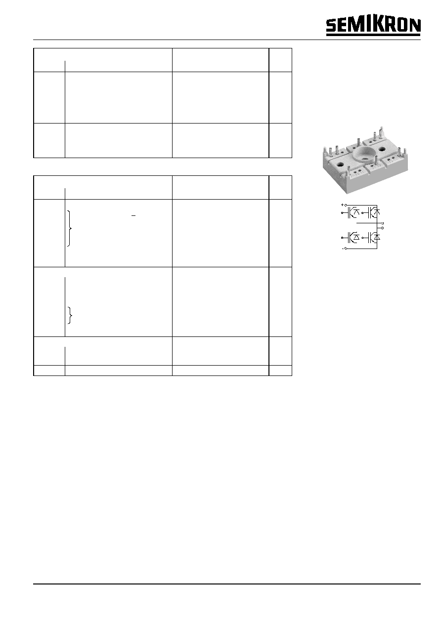
Case
T 5
SEMITOP
Æ
2
IGBT Module
SK 8 GH 062
Preliminary Data
Features
∑
Compact design
∑
One screw mounting
∑
Heat transfer and isolation
through direct copper bonded
aluminium oxide ceramic (DCB)
∑
N channel, epitaxial silicon
structure (PT Punch-through
IGBT)
∑
High short circuit capability
∑
Fast and soft inverse CAL-
diodes
Typical Applications
∑
Switching (not for linear use)
∑
Inverter
∑
Switched mode power supplies
∑
UPS
1)
T
h
= 25 ∞C, unless otherwise
specified
2)
CAL = Controlled Axial Lifetime
Technology ( soft and fast recovery)
3)
Thermal resistance junction to
heatsink
Case
page 4
GH
2
000111
© by SEMIKRON
SK 8 GH 062
0,01
0,1
1
0
10
20
30
40
V
CE
V
C
nF
C
ies
C
oes
C
res
8GH062.xls - 10
0
0,2
0,4
0,6
0,8
1
0
200
400
600
800
R
G
E
mWs
E
on
E
off
8GH062.xls - 8
0
2
4
6
8
10
12
14
16
18
20
0
10
20
30
40
Q
Gate
nC
V
GE
V
100V
300V
8GH062.xls - 9
0
0,2
0,4
0,6
0,8
1
0
2
4
6
8
10
12
I
C
A
E
mWs
E
on
E
off
8GH062.xls - 7
0
2
4
6
8
10
0
1
2
3
4
5
V
CE
V
I
C
A
17V
15V
13V
11V
9V
7V
8GH062.xls - 6
0
2
4
6
8
10
0
1
2
3
4
5
V
CE
V
I
C
A
17V
15V
13V
11V
9V
7V
8GH062.xls - 5
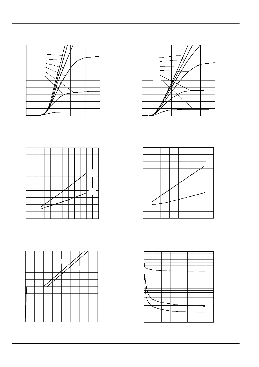
Fig. 7 Turn-on /-off energy = f (I
C
)
Fig. 8 Turn-on /-off energy = f (R
G
)
Fig. 5 Typ. output characteristic, t
p
= 80
µ
s; 25 ∞C
Fig. 6 Typ. output characteristic, t
p
= 80
µ
s; 125 ∞C
Fig. 9 Typ. gate charge characteristic
Fig. 10 Typ. capacitances vs. V
CE
V
GE
= 0 V
f = 1 MHz
T
j
= 125 ∞C
V
CC
= 300 V
V
GE
= ± 15 V
R
G
= 200
T
j
= 125 ∞C
V
CC
= 300 V
V
GE
= ± 15 V
I
C
= 5 A
I
Cpuls
= 5 A
© by SEMIKRON
000111
3
I
:\M
A
R
K
E
T
IN
\F
R
A
ME
D
A
T\
dat
bl
\B
17
-S
em
i
t
op
\sk8
gh0
62.
fm
0
0,02
0,04
0,06
0,08
0,1
0,12
0
2
4
6
8
10
I
F
A
E
offD
mJ
500
300
700
100
R
G
=
150
8GH062.xls - 13
10
100
1000
10000
0
200
400
600
800
R
G
t
ns
t
doff
t
don
t
r
t
f
8GH062.xls - 12
10
100
1000
0
2
4
6
8
10
12
I
C
A
t
ns
t
doff
t
don
t
r
t
f
8GH062.xls - 11
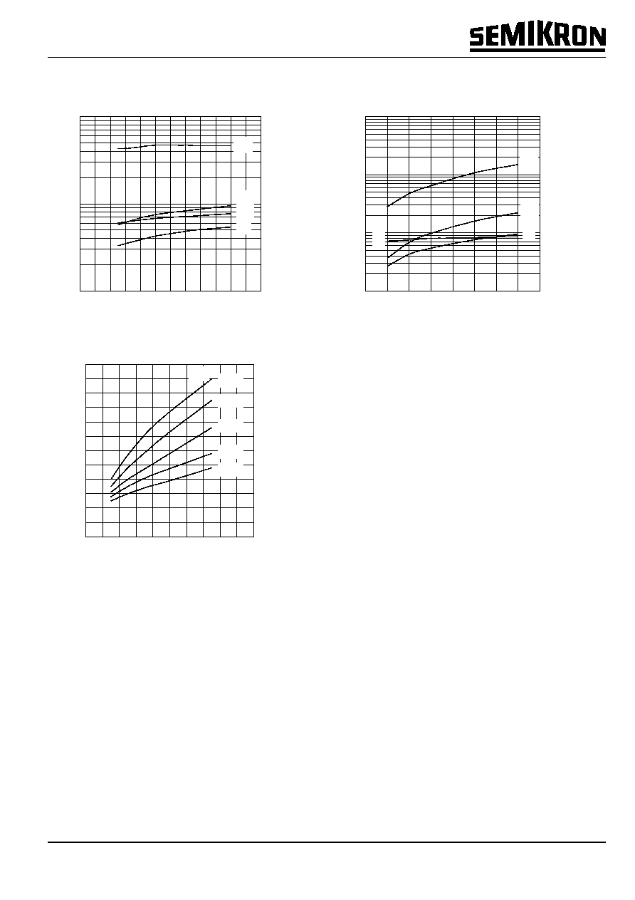
Fig. 11 Typ. switching times vs. I
C
Fig. 12 Typ. switching times vs. gate resistor R
G
Fig. 13 Diode turn-off energy dissipation per pulse
T
j
= 125 ∞C
V
CC
= 300 V
V
GE
= ± 15 V
I
C
= 5 A
induct. load
T
j
= 125 ∞C
V
CC
= 300 V
V
GE
= ± 15 V
R
Gon
= 200
R
Goff
= 200
induct. load
V
CC
= 300 V
T
j
= 125 ∞C
V
GE
= ± 15 V