© by SEMIKRON
B 11 ≠ 25
0898
1)
T
h
= heatsink temperature
2)
Freely suspended or mounted on an insulator
3)
Mounted on a painted metal sheet of min. 250 x 250 x 1 mm
V
RRM
V
RSM
I
D
(T
h
1)
= . . . įC)
V
V
33 A (110 įC)
53 A (100 įC)
83 A (95 įC)
400
800
1200
1400
1600
1800
500
900
1300
1600
1700
1900
SKD 33/04
SKD 33/08
SKD 33/12
SKD 33/14
SKD 33/16
SKD 33/18
SKD 53/04
SKD 53/08
SKD 53/12
SKD 53/14
SKD 53/16
SKD 53/18
SKD 83/04
SKD 83/08
SKD 83/12
SKD 83/14
SKD 83/16
SKD 83/18
Symbol Conditions
SKD 33
SKD 53 SKD 83
Units
I
D,
I
DCL
(T
h
1)
= . . . įC)
T
amb
= 45 įC; isolated
2)
chassis
3)
P5A/100
R4A/120
P1A/120
T
amb
= 35 įC, P1A/120F
36
(106)
4
16
24
25
34
50
53
(100)
4
18
27
29
39
63
83
(95)
4
20
32
34
48
83
A
įC
A
A
A
A
A
A
I
FSM
i
2
t
T
vj
= 25 įC; 10 ms
T
vj
= 150 įC; 10 ms
T
vj
= 25 įC; 8,3 ... 10 ms
T
vj
= 150 įC; 8,3 ... 10 ms
300
240
450
290
370
270
685
365
700
560
2 450
1 570
A
A
A
2
s
A
2
s
V
F
V
(TO)
r
T
I
RD
T
vj
= 25 įC; (I
F
= . . . A); max.
T
vj
= 150 įC
T
vj
= 150 įC
T
vj
= 25 įC; V
RD
= V
RRM
T
vj
= 150 įC;
V
RD
= V
RRM
1,60 (50)
0,8
18
0,2
4
1,50 (50)
0,8
13
0,2
4
1,45 (80)
0,8
7,5
0,2
4
V
V
m
mA
mA
R
thjh
R
thja
per diode
total
isolated
2)
chassis
3)
P5A/100
R4A/120
P1A/120
P1A/120F
2,5
0,417
15,02
3,02
1,77
1,67
1,12
0,67
1,9
0,317
14,92
2,92
1,67
1,57
1,02
0,57
1,4
0,233
14,83
2,83
1,58
1,48
0,93
0,48
įC/W
įC/W
įC/W
įC/W
įC/W
įC/W
įC/W
įC/W
T
vj
T
stg
≠ 40 ... + 150
≠ 40 ... + 125
įC
įC
V
isol
T
solder
M
1
a
w
a. c. 50 Hz; r.m.s; 1 s/1 min
10 s
Case to heatsink SI units
US units
3600 / 3000
250 Ī 10
2 Ī 15 %
18 Ī 15 %
5
.
9,81
30
V~
įC
Nm
lb. in.
m/s
2
g
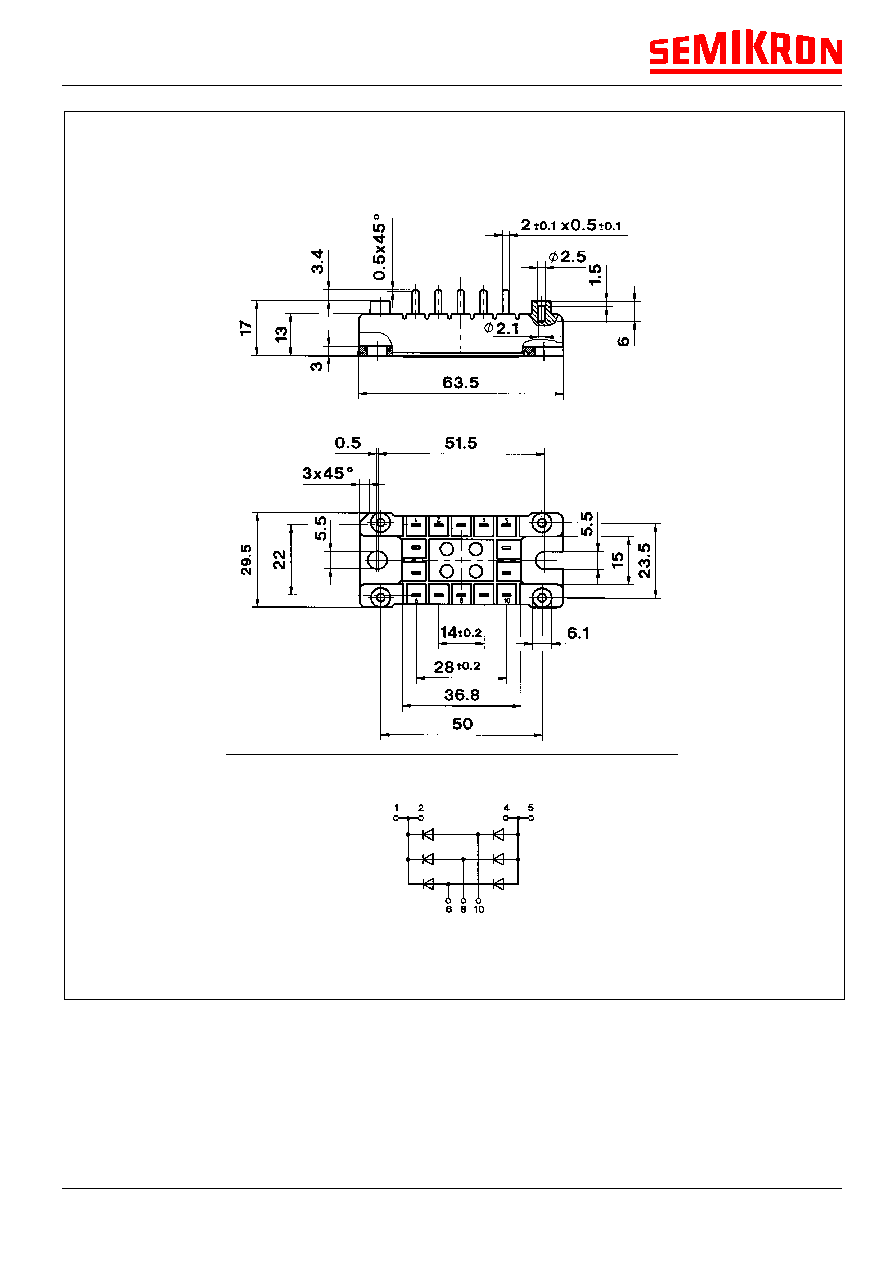
Case
G 55
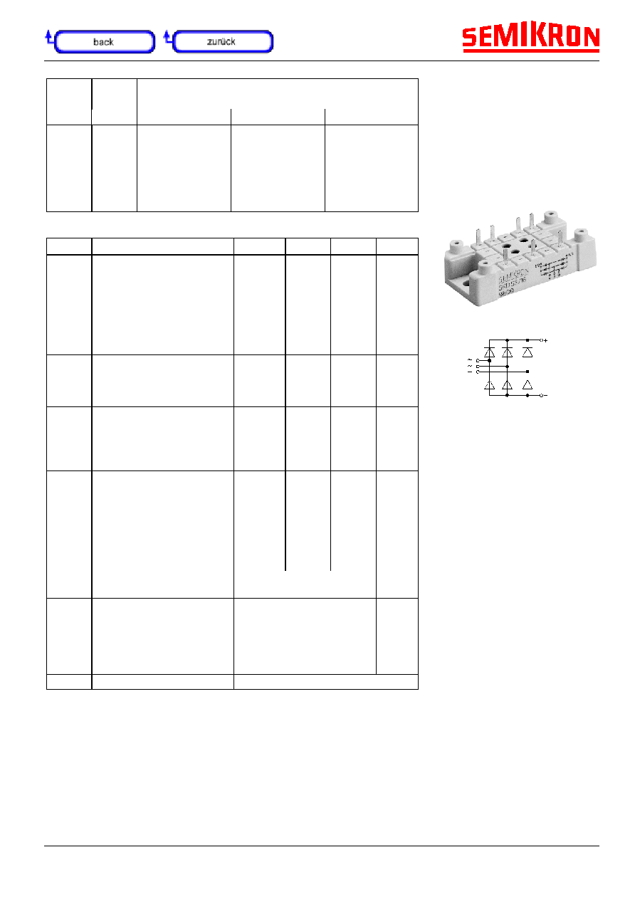
Power Bridge Rectifiers
SKD 33
SKD 53
SKD 83
Preliminary Data
Features
∑
Glass passivated silicon chips
∑
Low thermal impedance through
use of direct copper bonded
aluminum substrate (DCB) base
plate
∑
Blocking voltage up to 1800 V
∑
Suitable for PCB mounting and
wave soldering
∑
For applications with high
vibrations we recommend to
fasten the bridge to the pcb with
4 selftapping screws
∑
UL recognition applied for
Typical Applications
∑
Three phase rectifiers for power
supplies
∑
Input rectifiers for variable
frequency drives
∑
Rectifiers for DC motor field
supplies
∑
Battery charger rectifiers
© by SEMIKRON
B 11 ≠ 26
0898
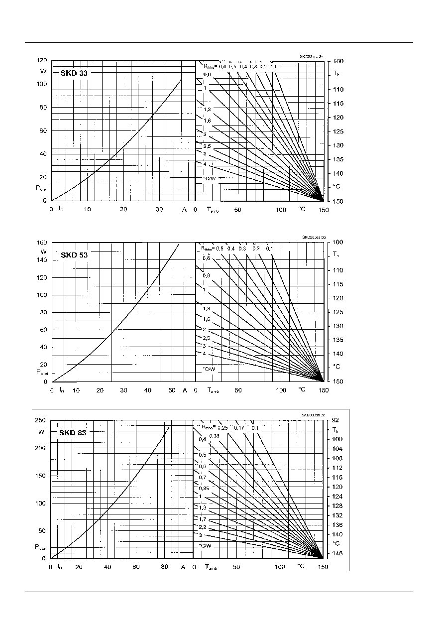
Fig. 3 a Power dissipation vs. output current and case temperature
Fig. 3 c Power dissipation vs. output current and case temperature
Fig. 3 b Power dissipation vs. output current and case temperature