 | –≠–ª–µ–∫—Ç—Ä–æ–Ω–Ω—ã–π –∫–æ–º–ø–æ–Ω–µ–Ω—Ç: SKIC6001 | –°–∫–∞—á–∞—Ç—å:  PDF PDF  ZIP ZIP |
SKIC 6001
by SEMIKRON
000913
1 / 4
Absolute Maximum Ratings (Ta = 25 ∞C)
Symbol
Term
Values
Units
V
DD15V
15 V supply voltage
(reference for output signals)
18
V
V
DD5V
5 V supply voltage
(reference for input signals)
6
V
V
iH
input signal voltage (HIGH) max.
V
DD5V
+ 0,3
V
V
iL
input signal voltage (LOW) min.
GND - 0,3
V
f
sw
switching frequency
50
kHz
T
op
/ T
stg
operating/storage temp.
-40...+ 85
∞C
Electrical Characteristics (Ta = 25 ∞C)
1)
Symbol
Term
Values
Units
V
DD15V
15 V supply voltage
15
±
5%
V
V
DD5V
5 V supply voltage
5
±
5%
V
I
S5V
supply current (V
DD5V
); typ
4)
5-10
mA
I
S15V
supply current (V
DD15V
); typ
4)
20-30
mA
t
d
propagation time
125
ns
t
TDswitch
2) 3)
dead time interlock; typ.
off, 1, 2, 3, 4
µ
s
t
supswitch
short pulse suppression TOP-BOT
depending on input current
for input resistor of 4.75k
70
ns
V
SU
supply under voltage monitoring using
V
DD15V
13,0
V
input signal TOP, BOTTOM,SELECT, TDT1, TDT2
ViT+
input threshold voltage (High)
3,7
V
V
iT-
input threshold voltage (Low)
1,5
V
R
down
internal pull down resistor (TOP;
BOTTOM)
66
±
2
k
R
up
internal pull up resistor (SELECT;
TDT1; TDT2)
66
±
2
k
ERROR Input Signals
V
ET+
input threshold voltage (High)
> 3,7
V
V
ET-
input threshold voltage (Low)
< 1,5
V
R
EUp
internal pull down resistor
22
k
t
swOSC
oscillatory frequency DC/DC Converter
500
3)
kHz
t
Td
time of interlock of DC/DC Converter
250
ns
Output Signal Error
I
outmax
max. output current at V
DD5V
±
5
mA
V
outmax
max. output voltage
4,8
V
V
outmin
min. output voltage
0,22
V
SEMIDRIVER
IGBT Driver Circuit
SKIC 6001
Preliminary Data
Package SOP 28
Features
IGBT-3-phase bridge driver circuit
with protection functions
∑ Interlock of TOP and BOTTOM
switches in each halfbridge
∑ Short pulse suppression
∑ Supply undervoltage protection
∑ Generation of the system clock
∑ Integrated DC/DC-converter
driver circuit
∑ Error monitoring
Typical Applications
∑ Driving of IGBTs
- for 3-phase bridge
configuration
- due to isolation (magnetic
transformer, optocoupler) can
be used for voltages > 1200 V
and high power applications
1)
Values for V
DD15V
;V
DD5V
;f
sw
=25kHz
2)
input "SELECT" = LOW
= no interlock
3)
with f
sw
= 8 MHz at OSC1, OSC2
4)
stand by
SKIC 6001
by SEMIKRON
000913
2 / 4
1
2
3
4
28
27
26
25
24
5
6
23
7
22
8
21
9
20
10
11
12
13
14
19
18
17
16
15
SKI
C
6001
TDT2
OSC1
OSC2
CPOR
TRP
TRN
TDT1
SELECT
ERROR
VDD5V
GND
VDD15V
RESET
ERRINT
GND
BI1
TI1
BI2
TI2
BI3
TI3
BOT3
TOP3
BOT2
TOP2
BOT1
TOP1
VDD5V
Pin-No.
Typ
1)
Name
Description
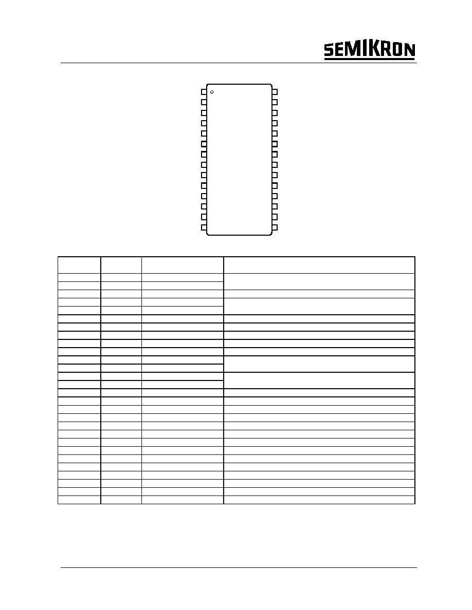
1
CON
TDT2
2
CON
TDT1
determine interlock time for 1, 2, 3 and 4
µ
s,
is only active if interlock mode is chosen with selector
3
CON
CPOR
Power On Reset, connect to 5V or C to GND for delay
4
CON
OSC1
5
CON
OSC2
oscillator connection for external 8MHz quartz resonator
(10M
in parallel for stability reasons is recommendable)
6
P
VDD5V
5V power supply
7
OUT
ERROR
output of error memory
8
IN
ERRINT
input of error memory (Active Low)
9
OUT
RESET
RESET signal, "0" : 0V, "1":5V (Active Low)
10
P
VDD15V
15V power supply
11
OUT
TRP
12
OUT
TRN
output of driver transistors for DC/DC Converter,
signal frequency is 500kHz, interlock time is 250ns
13
P
GND
14
P
GND
Ground
15
OUT
TOP1
driver output for TOP1 "0" : 0V, "1":5V
16
OUT
BOT1
driver output for BOT1 "0" : 0V, "1":5V
17
OUT
TOP2
driver output for TOP2 "0" : 0V, "1":5V
18
OUT
BOT2
driver output for BOT2 "0" : 0V, "1":5V
19
OUT
TOP3
driver output for TOP3 "0" : 0V, "1":5V
20
OUT
BOT3
driver output for BOT3 "0" : 0V, "1":5V
21
P
VDD5V
5V power supply
22
IN
TI3
control input "0" : 0V, "1":5V
23
IN
BI3
control input "0" : 0V, "1":5V
24
IN
TI2
control input "0" : 0V, "1":5V
25
IN
BI2
control input "0" : 0V, "1":5V
26
IN
TI1
control input "0" : 0V, "1":5V
27
IN
BI1
control input "0" : 0V, "1":5V
28
CON
SELECT
interlock optional "0" : 0V, "1":5V
1)
CON...Configuration pin, P..Power Supply, IN...Input, OUT...Output
Fig. 1
PIN Array SKIC 6001
SKIC 6001
by SEMIKRON
000913
3 / 4
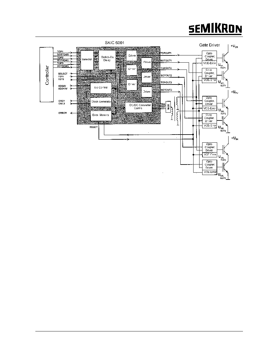
U
CE,ERR
, U
B,ERR
Figure 2: System Configuration of a Propulsion Control with SKIC6001 without Motor
Overview
The integrated intelligent controller circuit (SKIC6001)
is presented for the control of IGBTs, especially in a
3-phase bridge, for high power applications and
frequencies up to 50kHz. Fig. 2 shows the functional
block diagram of the control IC for a propulsion
control. It consists of a digital control unit, mostly a
microprocessor (µP), the control IC (SKIC 6001), a
potential separation (ferrite signal transformer or
opto-couplers), the gate driver stages, an IGBT
halfbridge and a consumer (as e.g. a motor).
By means of the digital unit a pulse frequency
modulation of the IGBT driver signals is possible and,
therefore, a power control of the consumer can be
realized. The developed control circuit contains the
signal processing, power supply, the driving and
monitoring functions for IGBTs in a 3-phase bridge
application. A power supply of 5V and 15V is
necessary. The most important parts, functions and
connections are shown in Fig. 2:
∑ the forward branch with selector, switch on delay,
short pulse suppression, driver and signal
transformer to the secondary side (high voltage side)
∑ the backward branch with error detection and
processing
∑ the additional part with clock generator, power
supply control and dc/dc converter circuit
The control circuit has several inputs, some of them
with a Schmitt-trigger characteristic for increased
noise immunity. TOP1..3 and BOTTOM1..3 are the
main control inputs. A RESET is generated after all
inputs are LOW for 9
µ
s (active Low).
With the use of bidirectional opto-couplers the
information between primary and secondary side may
flow in both directions and high levels of dv/dt and
insulation are guaranteed (ferrite signal transformers
are also possible).
The high frequency dc/dc converter avoids the
requirement of an externally insulated power supply
to obtain the necessary voltage and power for the
IGBT gates. For this operation the dc/dc converter
circuit supplies a 15V signal with a frequency of
500kHz for three halfbridges.
An internal protection function of the SKIC 6001 is the
power supply control. The circuit will be blocked, if
the 15V-power supply drops under a value of
approximately 13,0V. Further error signals as e.g.
from the primary side (e.g. for short circuit:V
CE
) can be
fed to the input of ERRINT. All detected error signals
are processed in the control IC. The forward driver
signal is blocked or the IGBTs are turned off and an
error signal appears at the output of the
microprocessor. The error storage can be reset by a

SKIC 6001
by SEMIKRON
000913
4 / 4
RESET pulse which is generated, if the inputs (TOP,
BOTTOM) are LOW for 9
µ
s.
Functional description
Interlock
Fig. 3 demonstrates the right function of the interlock
of TOP-and BOTTOM-IGBT.
125 ns
Fig. 3 Interlock function
At first BOTTOM is turned off immediately after the
corresponding input signal (at 5µs), while TOP is
turned on with a delay of about 4µs (setting of
interlock 4µs). After 10µs both inputs become ,,on".
This is not a correct state (both IGBT ,,on" means
short circuit) and the reason is both outputs are
switched off. A switch on of BOTTOM is possible not
before TOP is ,,off" (at 25µs, interlock and delay time
about 1µs).
Fig. 4 shows the behavior, if the interlock function
isn't active (SELECT ,,low"). Both outputs react
immediately to the corresponding input (the
difference is the signal delay time of about 125 ns).
The interlock time may be chosen by connecting pin
TDT1 and TDT2 to GND (0) or 5V (1).
PIN
4
µ
µ
µ
µ
s
3
µ
µ
µ
µ
s
2
µ
µ
µ
µ
s
1
µ
µ
µ
µ
s
OFF
TDT1
1
1
0
0
X
TDT2
1
0
1
0
X
SEL
1
1
1
1
0
125ns
Fig. 4 Interlock function not active
Shortpulse suppression
A very short pulse can be suppressed by limiting the
control input current. Thus with a 4.75k
resistance
shorter pulse than 70ns can be suppressed. This
gives a higher noise immunity.
DC-DC-Converter-Control signals
Fig. 5 output driver signals of the dc/dc converter.
The interlock time is 250ns, the frequency is 500kHz.
This technical information specifies devices but promises no characteristics. No warranty or guarantee
expressed or implied is made regarding delivery, performance or suitability.