
© by SEMIKRON
000131
B 16 ≠ 23
Absolute Maximum Ratings
Symbol
Conditions
1)
Values
Units
Inverter
V
CES
V
GES
I
C
I
CM
I
F
= ≠I
C
I
FM
= ≠I
CM
T
heatsink
= 25 / 80 ∞C
t
p
< 1 ms; T
heatsink
= 25 / 80 ∞C
T
heatsink
= 25 / 80 ∞C
t
p
< 1 ms; T
heatsink
= 25 / 80 ∞C
600
± 20
22 / 15
44 / 30
36 / 24
72 / 48
V
V
A
A
A
A
Bridge Rectifier
V
RRM
I
D
I
FSM
I
2
t
T
heatsink
= 80 ∞C
t
p
= 10 ms; sin. 180 ∞, T
j
= 25 ∞C
t
p
= 10 ms; sin. 180 ∞, T
j
= 25 ∞C
800
25
370
680
V
A
A
A
2
s
T
j
T
stg
V
isol
AC, 1 min.
≠ 40 . . . + 150
≠ 40 . . . + 125
2500
∞C
∞C
V
Characteristics
Symbol
Conditions
1)
min.
typ.
max.
Units
IGBT - Inverter & Chopper
V
CEsat
t
d(on)
t
r
t
d(off)
t
f
E
on
+ E
off
C
ies
R
thjh
I
C
= 15 A
T
j
= 25 (125)
∞
C
V
CC
= 300 V; V
GE
= ± 15 V
I
C
= 15 A; T
j
= 125
∞
C
R
gon
= R
goff
= 68
inductive load
V
CE
= 25 V; V
GE
= 0 V, 1 MHz
per IGBT
≠
≠
≠
≠
≠
≠
≠
≠
2,1(2,2)
35
50
250
500
2,2
0,8
≠
2,7(2,8)
70
100
370
750
≠
≠
2,0
V
ns
ns
ns
ns
mJ
nF
K/W
Diode
2)
- Inverter
V
F
= V
EC
V
TO
r
T
I
RRM
Q
rr
E
off
R
thjh
I
F
= 25 A
T
j
= 25 (125)
∞
C
T
j
= 125 ∞C
T
j
= 125 ∞C
I
F
= 25 A, V
R
= ≠ 300 V
di
F
/dt = ≠ 500 A/
µ
s
V
GE
= 0 V, T
j
= 125 ∞C
per diode
≠
≠
≠
≠
≠
≠
≠
1,45(1,4)
0,85
22
25
2,5
0,75
≠
1,7(1,7)
0,9
32
≠
≠
≠
1,7
V
V
m
A
µ
C
mJ
K/W
Diode
2)
- Chopper
V
F
= V
EC
V
TO
r
T
I
RRM
Q
rr
E
off
R
thjh
I
F
= 10 A
T
j
= 25 (125)
∞
C
T
j
= 125 ∞C
T
j
= 125 ∞C
I
F
= 10 A, V
R
= ≠ 300 V
di
F
/dt = ≠ 200 A/
µ
s
V
GE
= 0 V, T
j
= 125 ∞C
per diode
≠
≠
≠
≠
≠
≠
≠
1,45(1,4)
0,85
55
13
1,5
0,45
≠
1,7(1,7)
0,9
80
≠
≠
≠
2,7
V
V
m
A
µ
C
mJ
K/W
Diode - Rectifier
V
F
R
thjh
I
F
= 25 A, T
j
= 25 ∞C
per diode
≠
≠
1,2
≠
≠
2,6
V
K/W
Temperature Sensor
R
TS
T = 25 / 100 ∞C
1000 / 1670
Mechanical Data
M
1
Case
case to heatsink, SI Units
mechanical outline see page
B 16 ≠ 8
2
≠
M2
2,5
Nm
SKiiP 20 NAB 06 - SKiiP 20 NAB 06 I
MiniSKiiP 2
SEMIKRON integrated
intelligent Power
SKiiP 20 NAB 06
SKiiP 20 NAB 06 I
3)
3-phase bridge rectifier +
braking chopper +
3-phase bridge inverter
Case M2
UL recognized file no. E63532
∑
specification of shunts and
temperature sensor see part A
∑
common characteristics see
page B16≠3
Options
∑
also available with single phase
rectifier (called 20 NEB 06 or
20 NEB 06 I
3)
)
∑
also available with faster IGBTs
(type ... 063), data sheet on
request
1)
T
heatsink
= 25 ∞C, unless
otherwise specified
2)
CAL = Controlled Axial Lifetime
Technology (soft and fast
recovery)
3)
With integrated DC and/or AC
shunts
4)
accuracy of pure shunt, please
note that for DC shunt no
separate sensing contact is
used.
R
cs(dc)
R
cs(ac)
5 %
4)
1 %
16,5 m
10 m
B 16 ≠ 24
000131
© by SEMIKRON
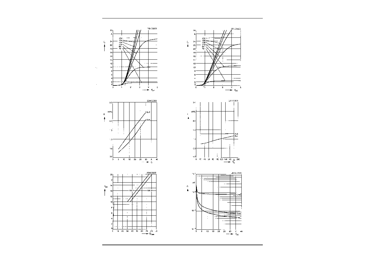
Fig. 3 Turn-on /-off energy = f (I
C
)
Fig. 4 Turn-on /-off energy = f (R
G
)
T
j
= 125 ∞C
V
CE
= 300 V
V
GE
= ± 15 V
I
C
= 15 A
T
j
= 125 ∞C
V
CE
= 300 V
V
GE
= ± 15 V
R
G
= 68
I
Cpuls
= 15 A
V
GE
= 0 V
f = 1 MHz
Fig. 1 Typ. output characteristic, t
p
= 80
µ
s; 25 ∞C
Fig. 2 Typ. output characteristic, t
p
= 80
µ
s; 125 ∞C
Fig. 5 Typ. gate charge characteristic
Fig. 6 Typ. capacitances vs. V
CE

© by SEMIKRON
0698
B 16 ≠ 3
Fig. 9 Turn-off safe operating area (RBSOA) of the IGBT
Fig. 10 Safe operating area at short circuit of the IGBT
T
j
=
150 ∞C
V
GE
= ± 15 V
t
sc
=
10
µ
s
L
ext
< 25 nH
T
j
=
150 ∞C
V
GE
= ± 15 V
Fig. 7 Rated current of the IGBT I
Cop
/ I
C
= f (T
h
)
T
j
= 150 ∞C
V
GE
=
15 V
0
0.2
0.4
0.6
0.8
1.0
1.2
0
25
50
75
100
125
150
ICop / IC
Mini0607
Th [∞C]
Fig. 11 Typ. freewheeling diode forward characteristic
Fig. 12 Forward characteristic of the input bridge diode
2. Common characteristics of MiniSKiiP
MiniSKiiP 600 V
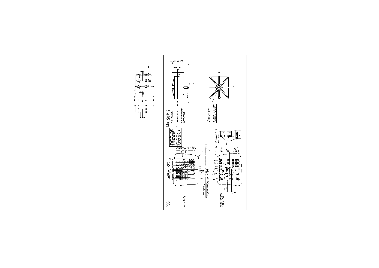
MiniSKiiP 2
SKiiP 20 NAB 06 ...
SKiiP 21 NAB 06 ...
SKiiP 20 NAB 12 ...
SKiiP 22 NAB 12 ...
Circuit
Case M2
Layout and connections for the
customer's printed circuit board
Note: The shunts are available
only by option I
-DC/A
Isw
0w
Isv
0v
0u
Isu
I+
B
-T
L3
L1
L2
+rect
-DC
-rect
g1
U
V
W
+T
+DC
g3
g5
g2
g6
g4
gB
+B
-B
Hauptanschluþ
power connector
control pin
Steueranschluþ