© by SEMIKRON
0698
B 16 ≠ 35
Absolute Maximum Ratings
Symbol
Conditions
1)
Values
Units
V
CES
V
GES
I
C
I
CM
T
heatsink
= 25 / 80 ∞C
T
heatsink
= 25 / 80 ∞C; t
p
= 1 ms
600
± 20
100 / 70
200 / 140
V
V
A
A
Inverse Diode
I
F
= ≠I
C
I
FM
= ≠I
CM
T
heatsink
= 25 / 80 ∞C
T
heatsink
= 25 / 80 ∞C; t
p
= 1 ms
130 / 88
260 / 186
A
A
V
isol
T
j
T
stg
AC, 1 min.
2500
≠ 40 . . . + 150
≠ 40 . . . + 125
V~
∞C
∞C
Characteristics
Symbol
Conditions
1)
min.
typ.
max.
Units
IGBT
V
CEsat
I
C
= 100 A; T
j
= 25 (125)
∞
C
≠
2.1(2.2) 2.7(2.8)
V
C
CHC
C
ies
C
oes
C
res
per IGBT
V
CE
= 25 V
V
GE
= 0 V
f = 1 MHz
≠
≠
≠
≠
≠
5.6
0.6
0.4
300
≠
≠
≠
pF
nF
nF
nF
t
d(on)
t
r
t
d(off)
t
f
E
on
+ E
off
R
thjh
V
CC
= 300 V; V
GE
= ± 15 V
I
C
= 100 A; T
j
= 125
∞
C
R
gon
= R
goff
= 11
inductive load
per IGBT
≠
≠
≠
≠
≠
≠
60
80
330
550
15
≠
120
160
500
830
≠
0.5
ns
ns
ns
ns
mJ
K/W
Diode
2)
V
F
= V
EC
V
TO
r
T
I
RRM
Q
rr
E
off
R
thjh
I
F
= 75 A
I
F
= 100 A T
j
= 25 (125)
∞
C
T
j
= 125 ∞C
T
j
= 125 ∞C
I
F
= 100 A; T
j
= 125
∞
C
V
R
= ≠ 300 V; V
GE
= 0 V
di
F
/dt = ≠ 800 A/
µ
s
per diode
≠
≠
≠
≠
≠
≠
≠
1.35(1.28)
1.5(1.45)
0.85
6
60
7.0
3.0
≠
≠
1.7(1.7)
0.9
6
≠
≠
≠
0.75
V
V
V
m
A
µ
C
mJ
K/W
Temperature Sensor
R
TS
T = 25 / 125 ∞C
1000 / 1670
Mechanical Data
M
1
Case
case to heatsink
mechanical outline see page
B 16 ≠ 10
2.5
≠
M7
3.5
Nm
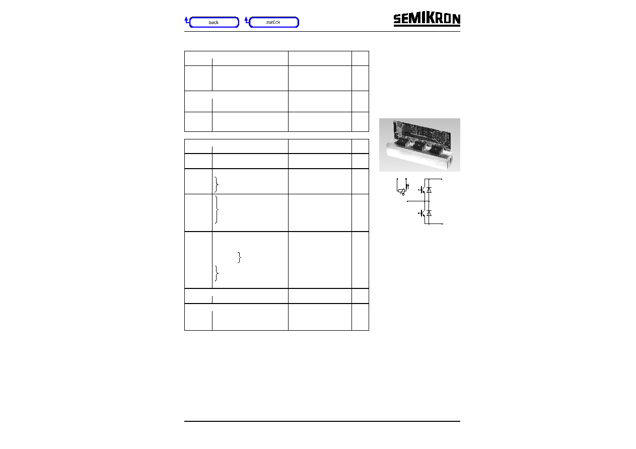
SKiiP 71 GB 06
MiniSKiiP 7
SEMIKRON integrated
intelligent Power
SKiiP 71 GB 06
IGBT
Half bridge
Case M7
UL recognized file no. E63532
∑
specification of temperature
sensor see part A
∑
Plug-in-mounting of the
customer PCB without soldering
∑
common characteristics see
page B 16 ≠ 3
Options
∑
also available with faster IGBTs
(type ... 063), data sheet on
request
1)
T
heatsink
= 25 ∞C, unless
otherwise specified
2)
CAL = Controlled Axial Lifetime
Technology (soft and fast
recovery)
-
+
~
+T
-T
B 16 ≠ 36
0698
© by SEMIKRON
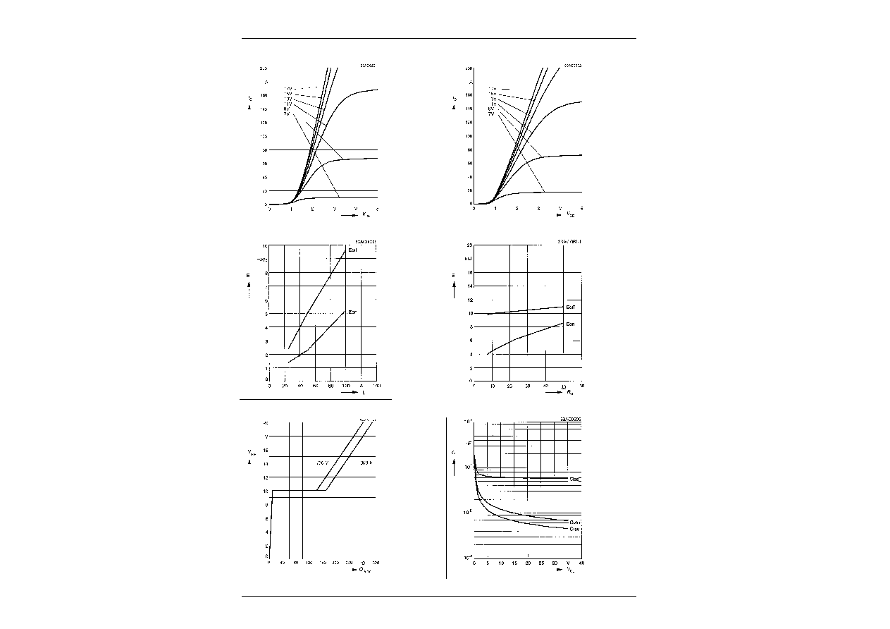
Fig. 3 Turn-on /-off energy = f (I
C
)
Fig. 4 Turn-on /-off energy = f (R
G
)
T
j
= 125 ∞C
V
CE
= 300 V
V
GE
= ± 15 V
I
C
= 100 A
T
j
= 125 ∞C
V
CE
= 300 V
V
GE
= ± 15 V
R
G
= 11
I
Cpuls
= 100 A
V
GE
= 0 V
f = 1 MHz
Fig. 1 Typ. output characteristic, t
p
= 80
µ
s; 25 ∞C
Fig. 2 Typ. output characteristic, t
p
= 80
µ
s; 125 ∞C
Fig. 5 Typ. gate charge characteristic
Fig. 6 Typ. capacitances vs. V
CE
© by SEMIKRON
0698
B 16 ≠ 3
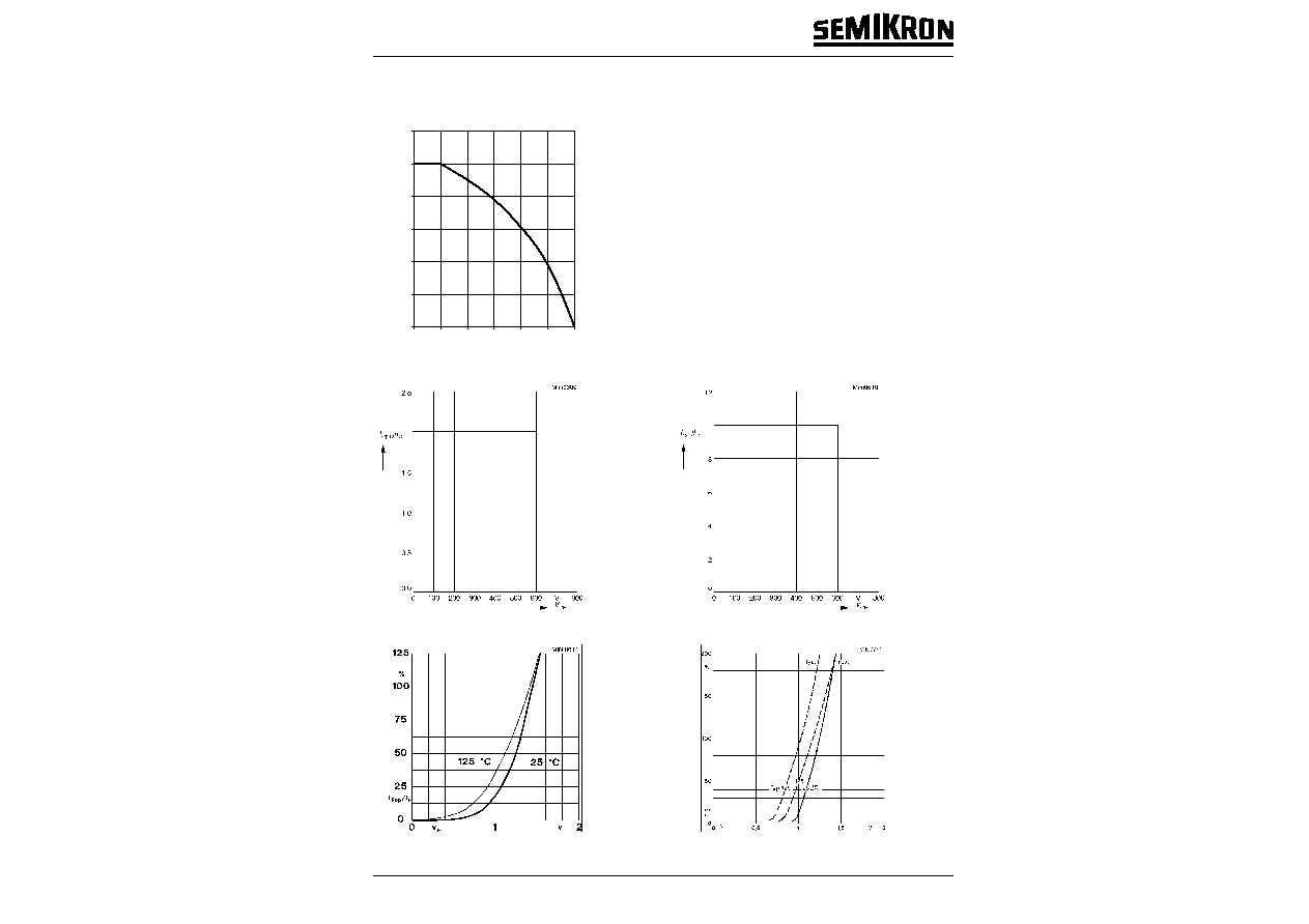
Fig. 9 Turn-off safe operating area (RBSOA) of the IGBT
Fig. 10 Safe operating area at short circuit of the IGBT
T
j
=
150 ∞C
V
GE
= ± 15 V
t
sc
=
10
µ
s
L
ext
< 25 nH
T
j
=
150 ∞C
V
GE
= ± 15 V
Fig. 7 Rated current of the IGBT I
Cop
/ I
C
= f (T
h
)
T
j
= 150 ∞C
V
GE
=
15 V
0
0.2
0.4
0.6
0.8
1.0
1.2
0
25
50
75
100
125
150
ICop / IC
Mini0607
Th [∞C]
Fig. 11 Typ. freewheeling diode forward characteristic
Fig. 12 Forward characteristic of the input bridge diode
2. Common characteristics of MiniSKiiP
MiniSKiiP 600 V
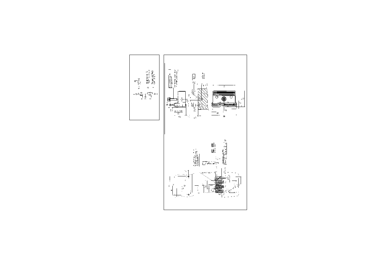
MiniSKiiP 7
SKiiP 71 GB 06
SKiiP 72 GB 12
Circuit
Case M7
Layout and connections for the
customer's printed circuit board