© by SEMIKRON
020315
1
SKiM 400 GD 126 DM
Absolute Maximum Ratings
Values
Symbol Conditions
1)
Units
V
CES
V
CGR
I
C
I
CM
V
GES
P
tot
T
j
, (T
stg
)
T
cop
V
isol
humidity
climate
R
GE
= 20 k
T
HS
= 25/70 ∞C
T
HS
= 25/70 ∞C; t
p
= 1 ms
per IGBT, T
HS
= 25 ∞C
max. case operating temperature
AC, 1 min.
IEC-EN 60721-3-3
IEC 68 T.1
1200
1200
330 / 255
660 / 510
± 20
935
≠40 ... +150 (125)
125
2500
40/125/56
V
V
A
A
V
W
∞C
∞C
V
Inverse Diode
I
F
= ≠I
C
I
FM
= ≠I
CM
I
FSM
I
2
t
T
HS
= 25/70 ∞C
T
HS
= 25/70 ∞C; t
p
= 1 ms
t
p
= 10 ms; sin.; T
j
= 150 ∞C
t
p
= 10 ms; T
j
= 150 ∞C
300 / 230
600 / 460
2200
24 200
A
A
A
A
2
s
Characteristics
Symbol Conditions
1)
min.
typ.
max.
Units
V
(BR)CES
V
GE(th)
I
CES
I
GES
V
CEsat
4)
V
GE
= 0, I
C
= 1 mA
V
GE
= V
CE
, I
C
= 4 mA
V
GE
= 0
V
CE
= V
CES
T
j
= 125 ∞C
V
GE
= 20 V, V
CE
= 0
I
C
= 300 A
V
GE
= 15 V;
T
j
= 25 (125) ∞C
V
CES
5,0
≠
≠
≠
≠
5,8
15
≠
1,7(2,0)
≠
6,5
≠
600
≠
V
V
mA
nA
V
C
ies
C
oes
C
res
L
CE
R
CC¥+ EE¥
V
GE
= 0
V
CE
= 25 V
f = 1 MHz
resistance, terminal-chip;
T
HS
= 25 ∞C
≠
≠
≠
≠
≠
23
1,6
1,6
≠
1,35
≠
20
≠
nF
nF
nF
nH
m
t
d(on)
t
r
t
d(off)
t
f
E
on
E
off
V
CC
= 600 V
V
GE
= +15 V / ≠15 V
3)
I
C
= 300 A, ind. load
R
Gon
= R
Goff
= 4,7
T
j
= 125 ∞C
≠
≠
≠
≠
≠
≠
250
55
800
120
17
32
≠
≠
≠
≠
≠
≠
ns
ns
ns
ns
mJ
mJ
Inverse Diode
8)
V
F
= V
EC
V
F
= V
EC
V
TO
r
T
I
RRM
Q
rr
I
F
= 200 A
V
GE
= 0 V;
I
F
= 100 A
T
j
= 25 (125) ∞C
T
j
= 125 ∞C
T
j
= 125 ∞C
I
F
= 350 A; T
j
= 25 (125) ∞C
2)
I
F
= 350 A; T
j
= 25 (125) ∞C
2)
≠
≠
≠
≠
≠
≠
2,3(2,1)
1,8(1,6)
1,1
5
TBD
TBD
2,6
≠
≠
V
V
V
m
A
µC
Thermal Characteristics
5)
R
thjh
R
thjhD
R'
thjc
6)
R'
thjcD
6)
per IGBT
per diode
per IGBT
per diode
≠
≠
≠
≠
≠
≠
≠
≠
0,134
0,19
TBD
TBD
∞C/W
∞C/W
∞C/W
∞C/W
Temperature Sensor
R
TS
tolerance
T = 25 ∞C / 100 ∞C
T = 25 ∞C / 100 ∞C
1,0 / 1,67
3,0 / 2,0
k
%
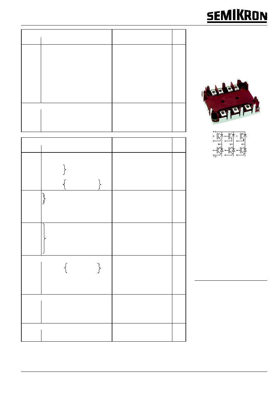
SKiM
Æ
4
IGBT Modules
SKiM 400 GD 126 DM
Preliminary Data
Features
∑
Trench gate IGBT with field stop
layer
∑
Low inductance case
∑
Fast & soft inverse CAL diodes
8)
∑
Isolated by AlN DCB (Direct
Copper Bonded) ceramic plate
∑
Pressure contact technology for
thermal contacts
∑
Spring contact system to attach
driver PCB to the control
terminals
∑
Integrated temperature sensor
Typical Applications
∑
Switched mode power supplies
∑
Three phase inverters for AC
motor speed control
∑
Switching (not for linear use)
1)
T
HS
= 25 ∞C, unless otherwise
specified
2)
TBD
3)
Use V
GEoff
= ≠5... ≠15 V
4)
Measured at chip level
5)
See mounting instructions
6)
Corresponding value. This value
cannot be measured. It is only given
for comparison.
8)
CAL = Controlled Axial Lifetime
Technology
GD
2
020315
© by SEMIKRON
SKiM 400 GD 126 DM
SKiM 4
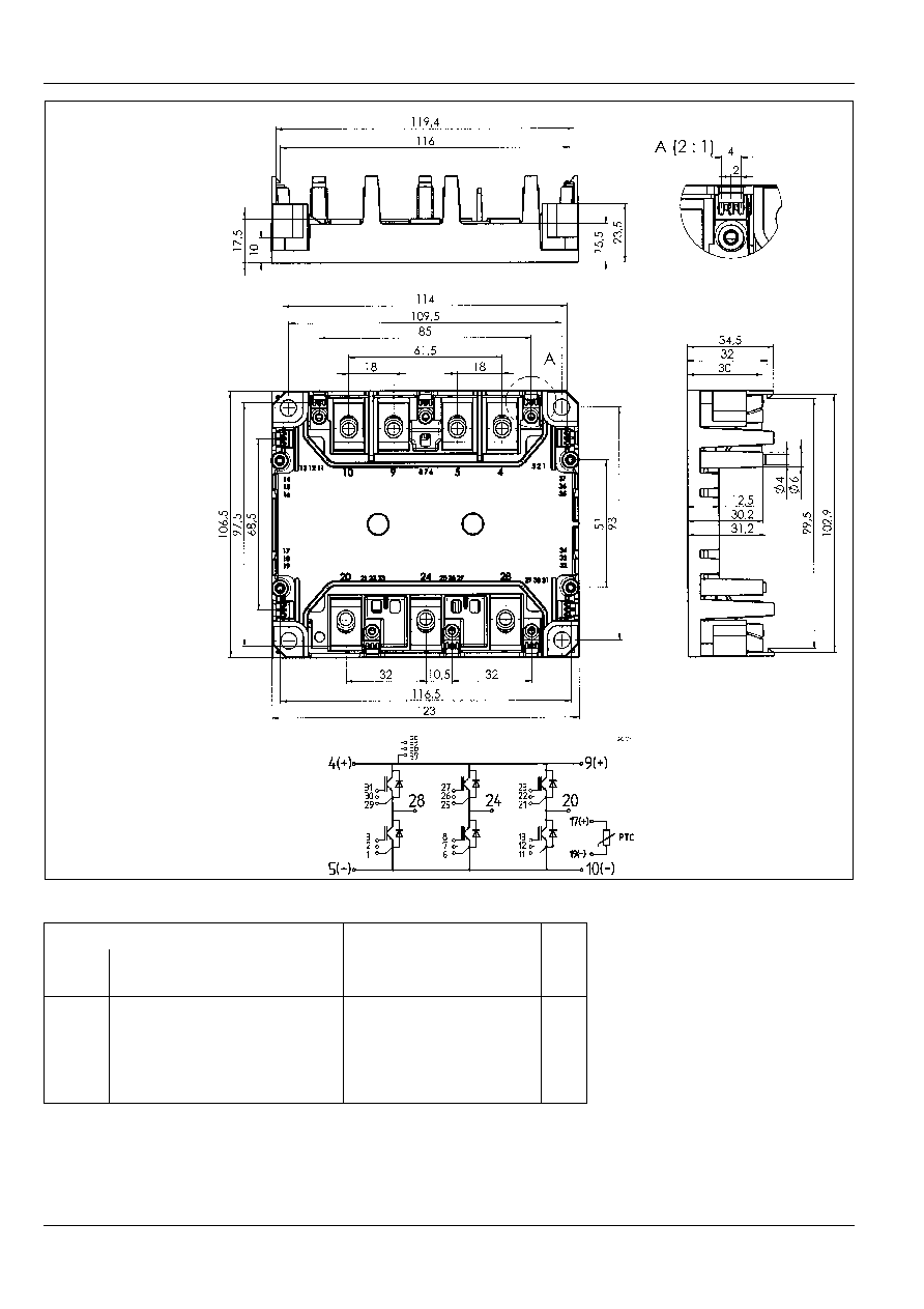
SKiM 400 GD 126 DM
Dimensions in mm
Case outline and circuit diagram
This is an electrostatic discharge sensitive device (ESDS).
Please observe the international standard IEC 747-1, Chapter IX.
Mechanical Data
Symbol Conditions
Values
Units
min.
typ.
max.
M
1
M
2
a
w
to heatsink, SI Units
(M5)
to heatsink, US Units
for terminals, SI Units
(M6)
for terminals, US Units
2
18
4
35
≠
≠
≠
≠
≠
≠
≠
≠
3
26
5
44
5x9,81
310
Nm
lb.in.
Nm
lb.in.
m/s
2
g
This technical information specifies semiconductor devices but promises no characteristics. No warranty or guarantee expressed or
implied is made regarding delivery, performance or suitability.