
Siemens AG
3
PCB relay for DC operation,
non-polarized, monostable
Features
q
General-application relay
q
Small size permitting high packing density
q
High vibration resistance
(10 to 38 Hz: 3.3 mm double amplitude
38 to 200 Hz: 10 g)
q
High shock resistance
30 g for sensitive and standard version
q
Sensitive version usable up to an ambient temperature of
85 ∞C
Typical applications
q
Security devices
q
Electric door openers
q
Duplex intercommunication systems
q
Measurement and control
Version
≠
Monostable, 1 winding
or
bistable, 1 winding, on request
≠
Terminal assignments symmetrical
or asymmetrical
and
5- or 6-pin version
≠
For 1 A or 3 A continuous current
≠
Standard or sensitive
≠
For printed circuit assembling
≠
Plastic case
≠
Immersion cleanable
ECR0987-Y
Approx. 1.5 x original size
Small Relay W11
1 changeover contact
V23101
w11_1we Seite 3 Montag, Juli 29, 1996 1:08 PM

4
Siemens AG
Small Relay W11
1 changeover contact
Dimension drawing (in mm)
Mounting hole layout
View on the terminals
Version: 6 pins
Version: 5 pins (without pin no. 6)
Basic grid 2.54 mm according to EN 60097 and DIN 40803, average
Terminal assignment
View on the terminals
Terminal assignment A symmetrical
Version: 6 pins
Terminal assignment B asymmetrical
Version: 6 pins
Version: 5 Pins
Version: 5 Pins
w11_1we Seite 4 Montag, Juli 29, 1996 1:08 PM

Siemens AG
5
Small Relay W11
1 changeover contact
*)
see also load limit curve
Load limit curve
I
= switching
current
U = switching
voltage
= recommended application field
Load limit curve: Quenching of the arc before the transit time
Contact data
Ordering code block 3
A201 or B201
A301 or B301
Contact material
AgPd, gold-plated
AgNi 10
Max. continuous current at max. ambient temperature
1 A
3 A
Maximum switching voltage
60 V≠
125 V~
Maximum switching capacity
DC voltage
*)
AC voltage
30 W
60 VA
72 W
360 VA
Recommended for load voltages greater than
1 V
5 V
Contact resistance (initial value) / measuring current / driver
voltage
100 m
/ 10 mA / 20 mV
100 m
/ 100 mA / 6 V
w11_1we Seite 5 Montag, Juli 29, 1996 1:08 PM
6
Siemens AG
Small Relay W11
1 changeover contact
Coil data
Nominal voltages
From 5 V≠ to 24 V≠
Typical nominal power consumption
standard version
sensitive version
450 mW
200 mW
Operative range/pickup class according to IEC 255-1-00 and
VDE 0435 Part 201
1/a
Maximum operating voltage
standard version
sensitive version
70% of the nominal voltage
75% of the nominal voltage
Minimum release voltage
10% of the nominal voltage
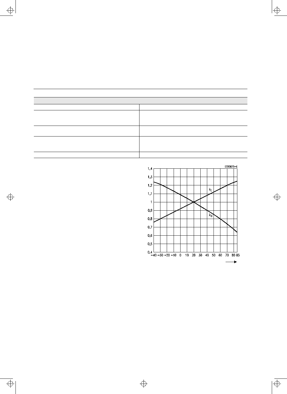
U
I
= Minimum voltage at 20 ∞C after pre-energizing
with nominal voltage without contact current
U
II
= Maximum continuous voltage at 20 ∞C
The operating voltage limits
U
I
and
U
II
are dependent on the
temperature according to the formulae:
U
I tamb
=
k
I
∑
U
I 20 ∞C
and
U
II tamb
=
k
II
∑
U
II 20 ∞C
t
amb
=
Ambient temperature
U
I tamb
=
Minimum voltage at ambient temperature,
t
amb
U
II tamb
=
Maximum voltage at ambient temperature,
t
amb
k
I
a.
k
II
=
Factors (temperature dependent), see diagram
Ambient temperature,
t
amb
[∞C]
w11_1we Seite 6 Montag, Juli 29, 1996 1:08 PM

Siemens AG
7
Small Relay W11
1 changeover contact
Coil versions
Nominal voltage
U
nom
Operating voltage range
at 20 ∞C
Resistance
at 20 ∞C
Coil number
Ordering code block 2
V≠
Minimum voltage,
U
I
V≠
Maximum voltage,
U
II
V≠
Standard version
1.5
1.25
2.6
6
±
0.6
001
3
2.1
4.7
20
±
2
002
5
3.5
7.9
56
±
5.6
003
6
4.2
9.5
80
±
8
004
9
6.3
14.2
180
±
18
005
12
8.4
19.0
320
±
32
006
24
16.8
38.0
1280
±
128
007
Sensitive version
1.5
1.13
3.6
12
±
1.2
101
3
2.25
7.1
45
±
4.5
102
5
3.75
11.6
120
±
12
103
6
4.5
14.2
180
±
18
104
9
6.75
21.2
400
±
40
105
12
9.0
28.0
700
±
70
106
24
18.0
56.0
2800
±
280
107
w11_1we Seite 7 Montag, Juli 29, 1996 1:08 PM