 | –≠–ª–µ–∫—Ç—Ä–æ–Ω–Ω—ã–π –∫–æ–º–ø–æ–Ω–µ–Ω—Ç: Edge118 | –°–∫–∞—á–∞—Ç—å:  PDF PDF  ZIP ZIP |

EDGE HIGH-PERFORMANCE PRODUCTS
1
www.semtech.com
Edge118
Low Skew
Clock Spreader
Description
Features
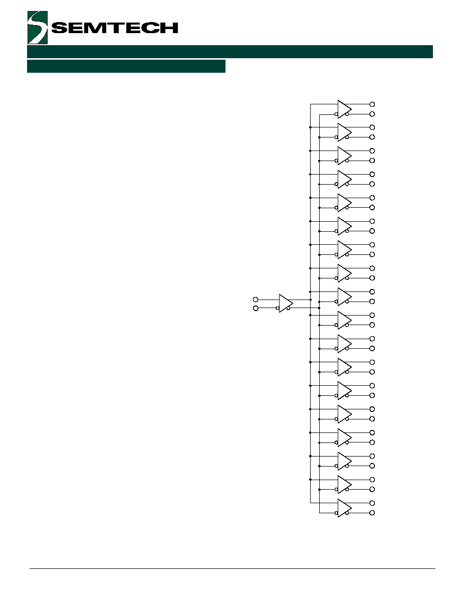
Functional Block Diagram
Applications
Revision 1/August 15, 2000
The Edge118 is a fully differential 1:18 clock spreader.
Manufactured in a high performance bipolar process,
the Edge118 is designed to accurately fan out a multitude
of clock signals with low channel to channel skew.
∑ Low Timing Error vs. Duty Cycle & Frequency
∑ Low Channel to Channel Skew
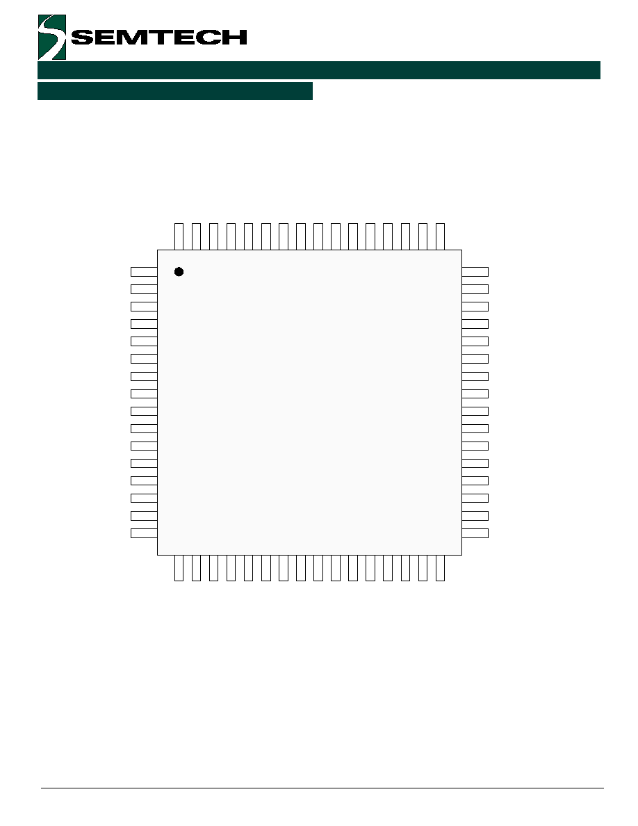
∑ Small Footprint (64 MQFP Package,
14 mm X 14 mm Body)
∑ Test Equipment
IN / IN*
OUT / OUT* 0
OUT / OUT* 1
OUT / OUT* 2
OUT / OUT* 3
OUT / OUT* 4
OUT / OUT* 5
OUT / OUT* 6
OUT / OUT* 7
OUT / OUT* 8
OUT / OUT* 9
OUT / OUT* 10
OUT / OUT* 11
OUT / OUT* 12
OUT / OUT* 13
OUT / OUT* 14
OUT / OUT* 15
OUT / OUT* 16
OUT / OUT* 17

2
2000 Semtech Corp.
www.semtech.com
EDGE HIGH-PERFORMANCE PRODUCTS
Edge118
PIN Description
e
m
a
N
n
i
P
#
n
i
P
n
o
i
t
p
i
r
c
s
e
D
*
N
I
,
N
I
8
,
6
.
l
a
n
g
i
s
t
u
p
n
i
l
a
i
t
n
e
r
e
f
f
i
D
*
0
T
U
O
,
0
T
U
O
*
1
T
U
O
,
1
T
U
O
*
2
T
U
O
,
2
T
U
O
*
3
T
U
O
,
3
T
U
O
*
4
T
U
O
,
4
T
U
O
*
5
T
U
O
,
5
T
U
O
*
6
T
U
O
,
6
T
U
O
*
7
T
U
O
,
7
T
U
O
*
8
T
U
O
,
8
T
U
O
*
9
T
U
O
,
9
T
U
O
*
0
1
T
U
O
,
0
1
T
U
O
*
1
1
T
U
O
,
1
1
T
U
O
*
2
1
T
U
O
,
2
1
T
U
O
*
3
1
T
U
O
,
3
1
T
U
O
*
4
1
T
U
O
,
4
1
T
U
O
*
5
1
T
U
O
,
5
1
T
U
O
*
6
1
T
U
O
,
6
1
T
U
O
*
7
1
T
U
O
,
7
1
T
U
O
3
,
1
1
6
,
3
6
0
6
,
8
5
5
5
,
7
5
4
5
,
2
5
9
4
,
1
5
7
4
,
5
4
2
4
,
4
4
1
4
,
9
3
6
3
,
8
3
5
3
,
3
3
9
2
,
1
3
8
2
,
6
2
3
2
,
5
2
2
2
,
0
2
7
1
,
9
1
5
1
,
3
1
0
1
,
2
1
.
s
l
a
n
g
i
s
t
u
p
t
u
o
L
C
E
l
a
i
t
n
e
r
e
f
f
i
D
s
e
i
l
p
p
u
S
r
e
w
o
P
D
N
G
,
1
2
,
8
1
,
4
1
,
1
1
,
7
,
2
,
7
3
,
4
3
,
0
3
,
7
2
,
4
2
,
3
5
,
0
5
,
6
4
,
3
4
,
0
4
2
6
,
9
5
,
6
5
y
l
p
p
u
S
r
e
w
o
P
e
v
i
t
i
s
o
P
E
E
V
4
6
,
8
4
,
2
3
,
6
1
,
9
y
l
p
p
u
S
r
e
w
o
P
e
v
i
t
a
g
e
N
N
D
T
,
P
D
T
5
,
4
s
n
o
i
t
c
e
n
n
o
C
e
d
o
i
D
l
a
m
r
e
h
T
3
2000 Semtech Corp.
www.semtech.com
EDGE HIGH-PERFORMANCE PRODUCTS
Edge118
PIN Description (continued)
VEE
OUT6*
GND
OUT6
OUT7
GND
OUT7*
OUT8*
GND
OUT8
OUT9
GND
OUT9*
OUT10*
GND
OUT10
OUT0
GND
OUT0*
TDP
TDN
IN
GND
IN*
VEE
OUT17*
GND
OUT17
OUT16
GND
OUT16*
VEE
VEE
OUT1
GND
OUT1*
OUT2*
GND
OUT2
OUT3
GND
OUT3*
OUT4*
GND
OUT4
OUT5
GND
OUT5*
OUT15*
GND
OUT15
OUT14
GND
OUT14*
OUT13*
GND
OUT13
OUT12
GND
OUT12*
OUT11*
GND
OUT11
VEE
64
49
33
17
1
4
2000 Semtech Corp.
www.semtech.com
EDGE HIGH-PERFORMANCE PRODUCTS
Edge118
Circuit Description
Chip Overview
The Edge118 is a clock distribution chip designed to
take one input signal (IN / IN*) and fan it out 18 times
to identical outputs (OUT / OUT*). The chip is designed
to minimize channel to channel skew and any timing jitter.
The part's wide fanout is extremely useful in applications
where many distinct copies of a signal are required on
one PC Board, and these signals must all be aligned.
This signal can be distributed without creating a
distribution tree using multiple devices.
Inputs
The input signal is differential, requiring 250 mV swings
for full performance operation. The inputs are ECL
compatible, but may also be operated over a common
mode voltage range between VEE + 1.3V and VCC ≠ .5V.
Outputs
The outputs are ECL compatible differential signals with
800 mV voltage swings centered around 1.3V below GND.
Operating Frequenc
y
The Edge118 is designed to maintain full performance
up to at least 1000 MHz and pass 500 ps pulses.
OUT 0
OUT 0*
OUT 1
OUT 1*
OUT 2
OUT 2*
OUT 3
OUT 3*
OUT 4
OUT 4*
OUT 5
OUT 5*
OUT 6
OUT 6*
OUT 7
OUT 7*
OUT 8
OUT 8*
OUT 9
OUT 9*
OUT 10
OUT 10*
OUT 11
OUT 11*
OUT 12
OUT 12*
OUT 13
OUT 13*
OUT 14
OUT 14*
OUT 15
OUT 15*
OUT 16
OUT 16*
OUT 17
OUT 17*
IN
IN*

5
2000 Semtech Corp.
www.semtech.com
EDGE HIGH-PERFORMANCE PRODUCTS
Edge118
Application Information
Power Supplies Decoupling
A .1
µ
F or .01
µ
F capacitor (with excellent high frequency
characteristics, is recommended between GND and VEE.
In addition, solid GND and VEE planes are recommended
to provide a low inductance path for the power supply
currents.
Output Terminations
For optimal results, all output pairs (used or unused)
should be terminated, and terminated in the same
manner.
Thermal Information
r
e
t
e
m
a
r
a
P
l
o
b
m
y
S
e
u
l
a
V
s
t
i
n
U
e
c
n
a
t
s
i
s
e
R
l
a
m
r
e
h
T
)
d
r
a
o
B
C
P
a
o
t
d
e
r
e
d
l
o
s
t
r
a
p
,
M
F
L
0
0
3
(
r
i
A
o
t
n
o
i
t
c
n
u
J
A
J
5
2
~
W
/
C
∞