1
www.semtech.com
EZ1082
10.0A Positive
Voltage Regulator
POWER MANAGEMENT
Revision 1, December 2000
The EZ1082 is a high performance positive voltage
regulator designed for use in applications requiring low
dropout performance at 10A. Additionally, the EZ1082
provides excellent regulation over variations in line, load
and temperature.
Features include 1.3V dropout at 10A, fast transient
response, internal current limiting and thermal shutdown
protection of the output device. The EZ1082 series are
three terminal regulators with fixed and adjustable
voltage options available in the popular TO-220
package.
The EZ1082 is an excellent choice for powering
microprocessor systems. Using an LDO eliminates
MOSFETs and inductors saving both space and cost. An
LDO also provides better transient response with no ripple
to the load.
u
Low dropout performance, 1.3V max.
u
Full current rating over line and temperature
u
Fast transient response
u
±2% total output regulation over line, load and
temperature
u
Adjust pin current max 90µA over temperature
u
Fixed/adjustable output voltage
u
Line regulation typically 0.015%
u
Load regulation typically 0.05%
u
TO-220 3 pin package
u
High current microprocessor supplies
u
Post regulators
u
Microprocessor systems
u
Medical equipment
u
Embedded systems
u
Post regulation for switching supplies
u
Telecommunication systems
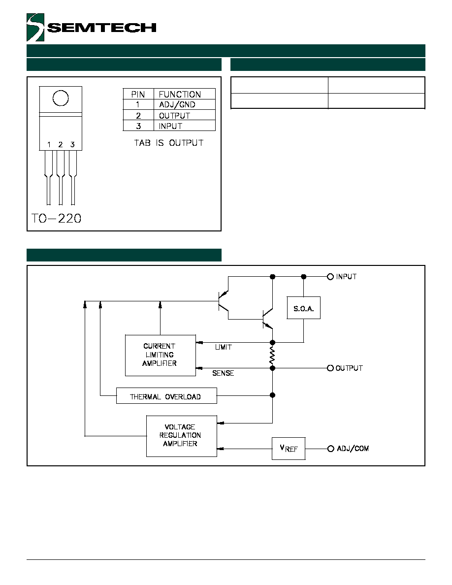
Fixed Voltage Regulator
Adjustable Voltage Regulator
Description
Features
Applications
Typical Application Circuit
VIN > 4.75V
VOUT = 3.45V
VOUT = 3.3V
VIN > 4.75V
U1
EZ1082
1
2
3
ADJ
OUT
IN
TAB
+
C2
10uF Tant. Min.
R1
133 Ohm, 1%
+
C1
10uF Tant.
U1
EZ1082-3.3
1
2
3
GND
OUT
IN
TAB
R2
232 Ohm, 1%
+
C1
10uF Tant.
+
C2
10uF Tant. Min
Notes:
(1) C1 needed if device is far from filter capacitors
(2) C2 minimum value required for stability
2
R
I
1
R
2
R
1
V
V
ADJ
REF
OUT
·
+
+
·
=

3
ã 2000 Semtech Corp.
www.semtech.com
EZ1082
POWER MANAGEMENT
NOTES:
(1) Low duty cycle pulse testing with Kelvin connections required.
(2) Bandwidth of 10 Hz to 10 kHz.
(3) 120 Hz input ripple (C
ADJ
for ADJ = 25µF).
(4) Over Temp. (O.T.) = over specified operating junction temperature range.
r
e
t
e
m
a
r
a
P
l
o
b
m
y
S
V
N
I
I
O
T
J
)
4
(
n
i
M
p
y
T
x
a
M
s
ti
n
U
t
n
e
rr
u
C
n
i
P
t
s
u
j
d
A
I
J
D
A
C
°
5
2
5
5
A
µ
.
T
.
O
0
9
t
n
e
rr
u
C
n
i
P
t
s
u
j
d
A
e
g
n
a
h
C
DI
J
D
A
.
T
.
O
2
.
0
5
A
µ
y
ti
li
b
a
t
S
e
r
u
t
a
r
e
p
m
e
T
T
S
V
5
A
5
.
0
.
T
.
O
5
.
0
%
t
n
e
rr
u
C
d
a
o
L
m
u
m
i
n
i
M
n
o
i
s
r
e
V
e
g
a
tl
o
V
j
d
A
I
O
V
5
.
T
.
O
5
0
1
A
m
e
s
i
o
N
t
u
p
t
u
O
S
M
R
)
2
(
V
N
C
°
5
2
3
0
0
.
0
V
%
O
o
it
a
R
n
o
it
c
e
j
e
R
e
l
p
p
i
R
)
3
(
R
A
V
5
A
0
.
0
1
.
T
.
O
0
6
2
7
B
d
Electrical Characteristics (Cont.)