1
www.semtech.com
EZ1117
0.8 & 1.0 Amp Positive
Voltage Regulators
POWER MANAGEMENT
Revision 3, May 2003
The EZ1117 series of high performance positive voltage
regulators are designed for use in applications requiring
low dropout performance at up to 0.8A.
Additionally, the EZ1117 series provides excellent
regulation over variations in line, load and temperature.
Outstanding features include low dropout performance
at rated current, fast transient response, internal
current limiting and thermal shutdown protection of the
output device.
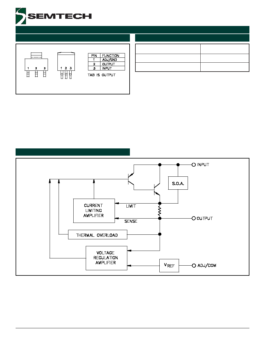
The EZ1117 series of three terminal regulators offer fixed
and adjustable voltage options available in the space
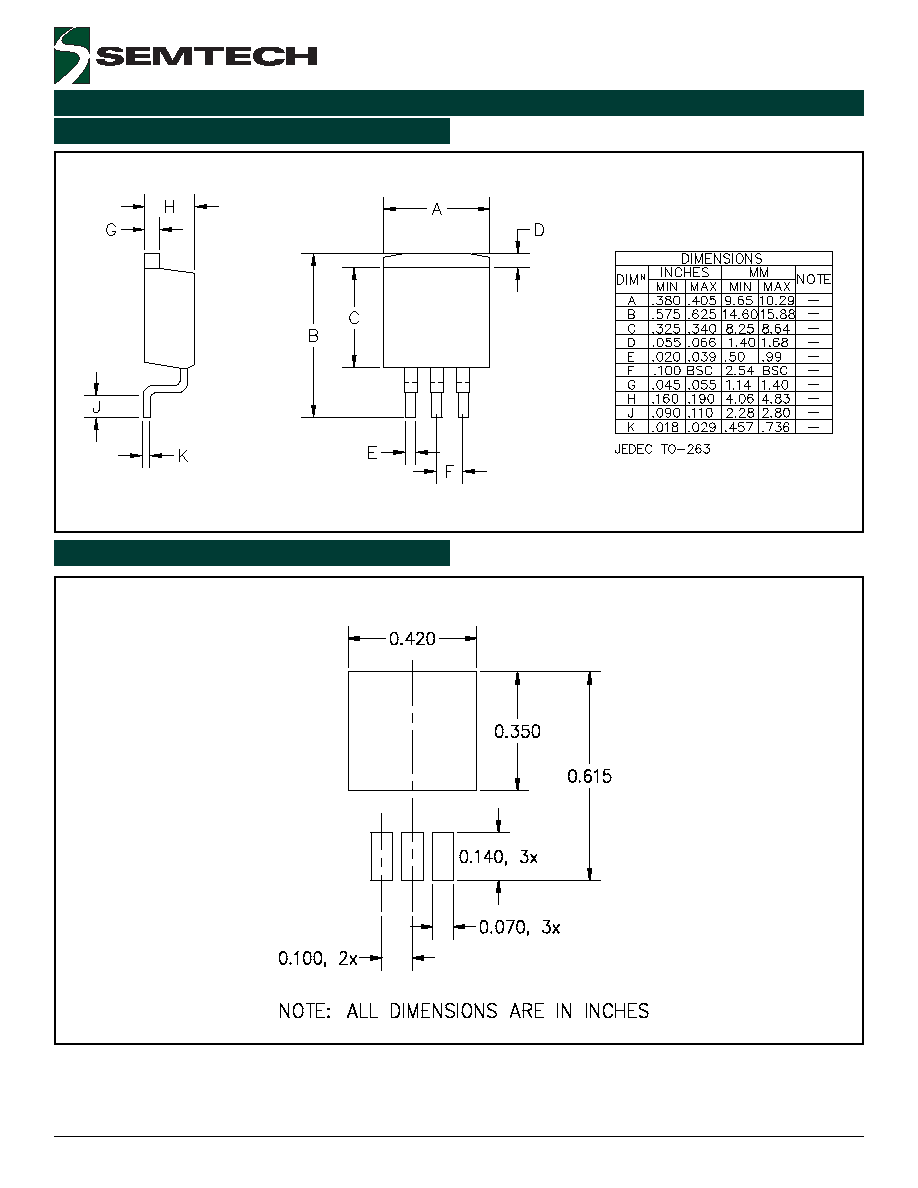
saving SOT-223 and TO-263 packages.
Low dropout performance: 1.2V max.
Full current rating over line and temperature
Fast transient response
±
2% total output regulation over line, load and
temperature
Adjust pin current max 90µA over temperature
Fixed/adjustable output voltage
Line regulation 0.2% max.
Load regulation 0.4% max.
SOT-223 and TO-263 packages
Low voltage microcontrollers
Switching power supply post-regulation
Description
Features
Applications
Fixed Voltage Regulator
Adjustable Voltage Regulator
Typical Application Circuit
VIN > 4.75V
VOUT = 3.45V
VOUT = 2.5V
VIN > 4.75V
U1
EZ1117
1
2
3
ADJ
OUT
IN
TAB
+
C2
10uF Tant. Min.
R1
133 Ohm, 1%
+
C1
10uF Tant.
U1
EZ1117-2.5
1
2
3
GND
OUT
IN
TAB
R2
232 Ohm, 1%
+
C1
10uF Tant.
+
C2
10uF Tant. Min
Notes:
(1) C1 needed if device is far from filter capacitors
(2) C2 minimum value required for stability
2
R
I
1
R
2
R
1
V
V
ADJ
REF
OUT
∑
+
+
∑
=
2
2003 Semtech Corp.
www.semtech.com
EZ1117
POWER MANAGEMENT
r
e
t
e
m
a
r
a
P
l
o
b
m
y
S
m
u
m
i
x
a
M
s
t
i
n
U
e
g
a
tl
o
V
y
l
p
p
u
S
t
u
p
n
I
V
N
I
7
V
n
o
it
a
p
i
s
s
i
D
r
e
w
o
P
P
D
d
e
ti
m
i
L
y
ll
a
n
r
e
t
n
I
W
e
s
a
C
o
t
n
o
it
c
n
u
J
e
c
n
a
t
s
i
s
e
R
l
a
m
r
e
h
T
3
2
2
-
T
O
S
3
6
2
-
O
T
C
J
5
1
3
W
/
C
∞
t
n
e
i
b
m
A
o
t
n
o
it
c
n
u
J
e
c
n
a
t
s
i
s
e
R
l
a
m
r
e
h
T
3
2
2
-
T
O
S
3
6
2
-
O
T
A
J
6
5
1
0
6
W
/
C
∞
e
g
n
a
R
e
r
u
t
a
r
e
p
m
e
T
n
o
it
c
n
u
J
g
n
it
a
r
e
p
O
T
J
5
2
1
o
t
0
C
∞
e
g
n
a
R
e
r
u
t
a
r
e
p
m
e
T
e
g
a
r
o
t
S
T
G
T
S
0
5
1
o
t
5
6
-
C
∞
.
c
e
S
0
1
)
g
n
ir
e
d
l
o
S
(
e
r
u
t
a
r
e
p
m
e
T
d
a
e
L
T
D
A
E
L
0
0
3
C
∞
)l
e
d
o
M
y
d
o
B
n
a
m
u
H
(
g
n
it
a
R
D
S
E
D
S
E
2
V
k
r
e
t
e
m
a
r
a
P
l
o
b
m
y
S
V
N
I
I
O
T
J
)
5
(
n
i
M
p
y
T
x
a
M
s
t
i
n
U
e
g
a
tl
o
V
t
u
p
t
u
O
)
1
(
V
O
V
5
A
m
O
C
∞
5
2
%
5
.
1
-
V
O
%
5
.
1
+
V
)
s
n
o
i
s
r
e
V
e
g
a
tl
o
V
d
e
x
i
F
(
.
T
.
O
%
2
-
%
2
+
e
g
a
tl
o
V
e
c
n
e
r
e
f
e
R
)
1
(
V
F
E
R
V
5
A
m
0
1
C
∞
5
2
1
3
2
.
1
0
5
2
.
1
9
6
2
.
1
V
)
n
o
i
s
r
e
V
e
g
a
tl
o
V
j
d
A
(
.
T
.
O
5
2
2
.
1
5
7
2
.
1
n
o
it
a
l
u
g
e
R
e
n
i
L
)
1
(
G
E
R
)
E
N
I
L
(
A
m
0
1
.
T
.
O
5
3
0
.
0
2
.
0
%
n
o
it
a
l
u
g
e
R
d
a
o
L
)
1
(
G
E
R
)
D
A
O
L
(
V
5
.
T
.
O
2
.
0
4
.
0
%
e
g
a
tl
o
V
t
u
o
p
o
r
D
)
2
(
)
1
(
V
D
A
m
0
0
1
A
m
0
0
5
A
m
0
0
8
.
T
.
O
0
0
.
1
5
0
.
1
0
1
.
1
0
1
.
1
5
1
.
1
0
2
.
1
V
ti
m
i
L
t
n
e
r
r
u
C
I
L
C
.
T
.
O
8
.
0
A
t
n
e
r
r
u
C
t
n
e
c
s
e
i
u
Q
n
o
i
s
r
e
V
e
g
a
tl
o
V
d
e
x
i
F
I
Q
V
5
.
T
.
O
0
1
3
1
A
m
t
n
e
i
c
if
f
e
o
C
e
r
u
t
a
r
e
p
m
e
T
T
C
.
T
.
O
5
0
0
.
0
C
∞
/
%
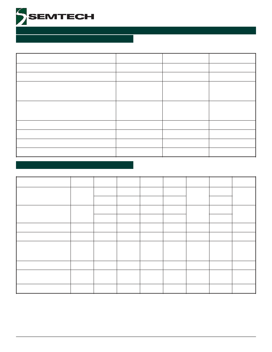
Unless otherwise specified: Adj. Option: V
IN
= 2.65V to 7.0V and I
O
= 10mA to I
RATED
. Fixed Options: I
O
= 0mA to I
RATED
, V
IN
(2.5V) = 3.9V to 7.0V.
Absolute Maximum Ratings
Electrical Characteristics
(6)
Exceeding the specifications below may result in permanent damage to the device, or device malfunction. Operation outside of the parameters specified
in the Electrical Characteristics section is not implied.

3
2003 Semtech Corp.
www.semtech.com
EZ1117
POWER MANAGEMENT
r
e
t
e
m
a
r
a
P
l
o
b
m
y
S
V
N
I
I
O
T
J
)
5
(
n
i
M
p
y
T
x
a
M
s
t
i
n
U
t
n
e
r
r
u
C
n
i
P
t
s
u
j
d
A
I
J
D
A
.
T
.
O
5
5
0
9
A
µ
t
n
e
r
r
u
C
n
i
P
t
s
u
j
d
A
e
g
n
a
h
C
I
J
D
A
.
T
.
O
2
.
0
5
A
µ
y
ti
li
b
a
t
S
e
r
u
t
a
r
e
p
m
e
T
T
S
.
T
.
O
5
.
0
%
t
n
e
r
r
u
C
d
a
o
L
m
u
m
i
n
i
M
n
o
i
s
r
e
V
e
g
a
tl
o
V
j
d
A
I
O
V
5
.
T
.
O
5
0
1
A
m
e
s
i
o
N
t
u
p
t
u
O
S
M
R
)
3
(
V
N
C
∞
5
2
3
0
0
.
0
V
%
O
o
it
a
R
n
o
it
c
e
j
e
R
e
l
p
p
i
R
)
4
(
R
A
V
5
I
D
E
T
A
R
.
T
.
O
0
6
2
7
B
d
NOTES:
(1) Low duty cycle pulse testing with Kelvin connections required.
(2)
V
OUT
,
V
REF
= 1%.
(3) Bandwidth of 10 Hz to 10kHz.
(4) 120Hz input ripple (C
ADJ
for ADJ = 25µF).
(5) O.T. = over specified operating junction temperature range.
(6) I
RATED
= 800mA.
Electrical Characteristics (Cont.)
(6)
Unless otherwise specified: Adj. Option: V
IN
= 2.65V to 7.0V and I
O
= 10mA to I
RATED
. Fixed Options: I
O
= 0mA to I
RATED
, V
IN
(2.5V) = 3.9V to 7.0V.