1
www.semtech.com
SC5205
150mA Ultra Low Dropout, Low
Noise Micropower Linear Regulator
POWER MANAGEMENT
PRELIMINARY
Revision 1, January 2001
The SC5205 is a 150mA ultra low dropout linear
regulator with a built in CMOS/TTL logic level enable
switch. It is designed specifically for battery powered
applications where low quiescent current and low
dropout are critical for battery longevity.
The SC5205 uses a Semtech proprietary internal PNP
device for the pass element, providing a low dropout
voltage of 165mV at a load of 150mA, while maintaining
a ground pin current of 2750µA.
The output noise is reduced by placing a 10nF capacitor
on pin 4 (bypass).
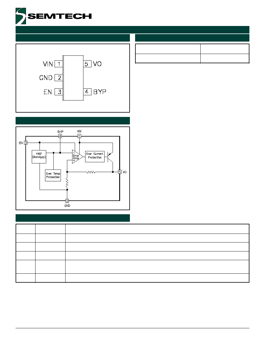
Each device contains a bandgap reference, error
amplifier, PNP pass element, thermal and current
limiting circuitry and resistor divider network for setting
output voltage.
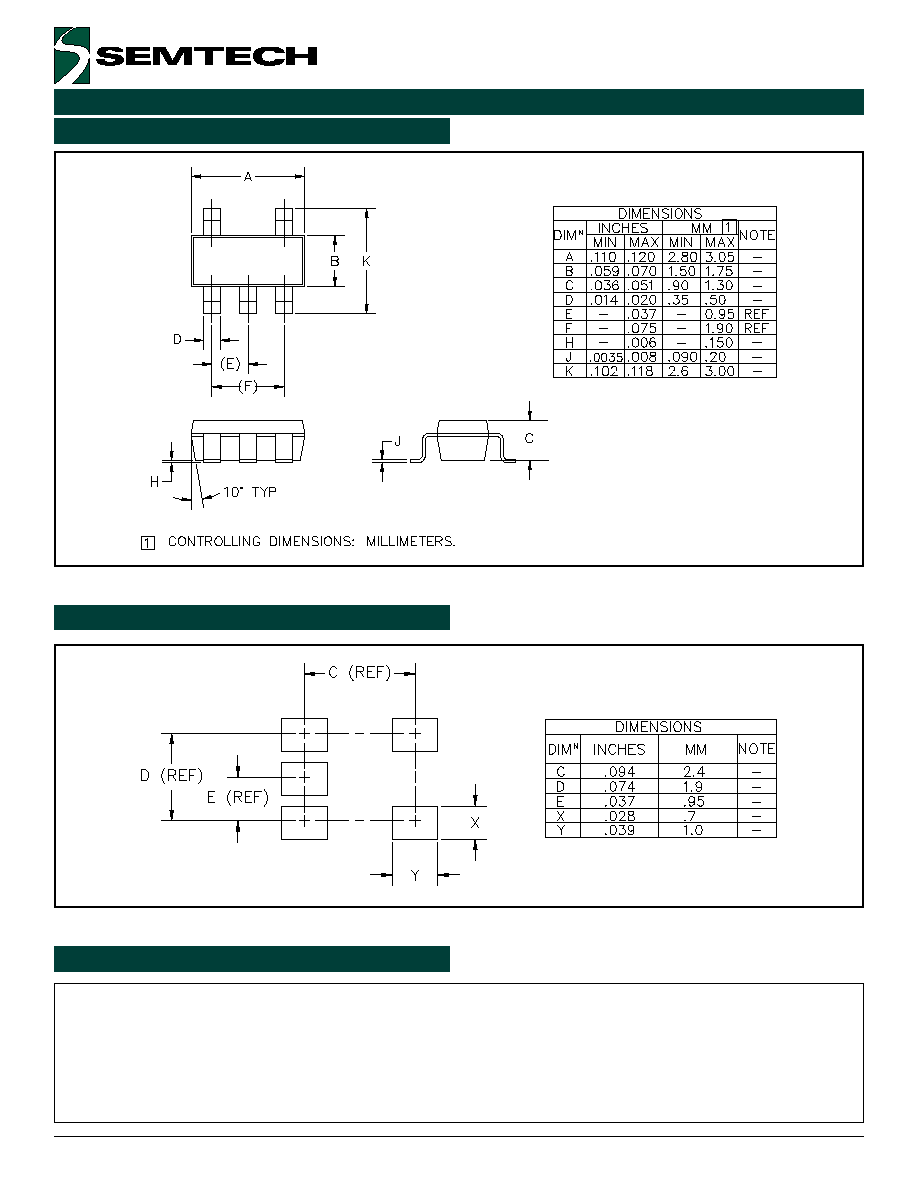
The SC5205 is packaged in a 5 pin SOT-23 surface mount
package for a very small footprint and it requires only a
1µF capacitor on the output and a 0.01µF on the bypass
pin for a minimum amount of external components.
u
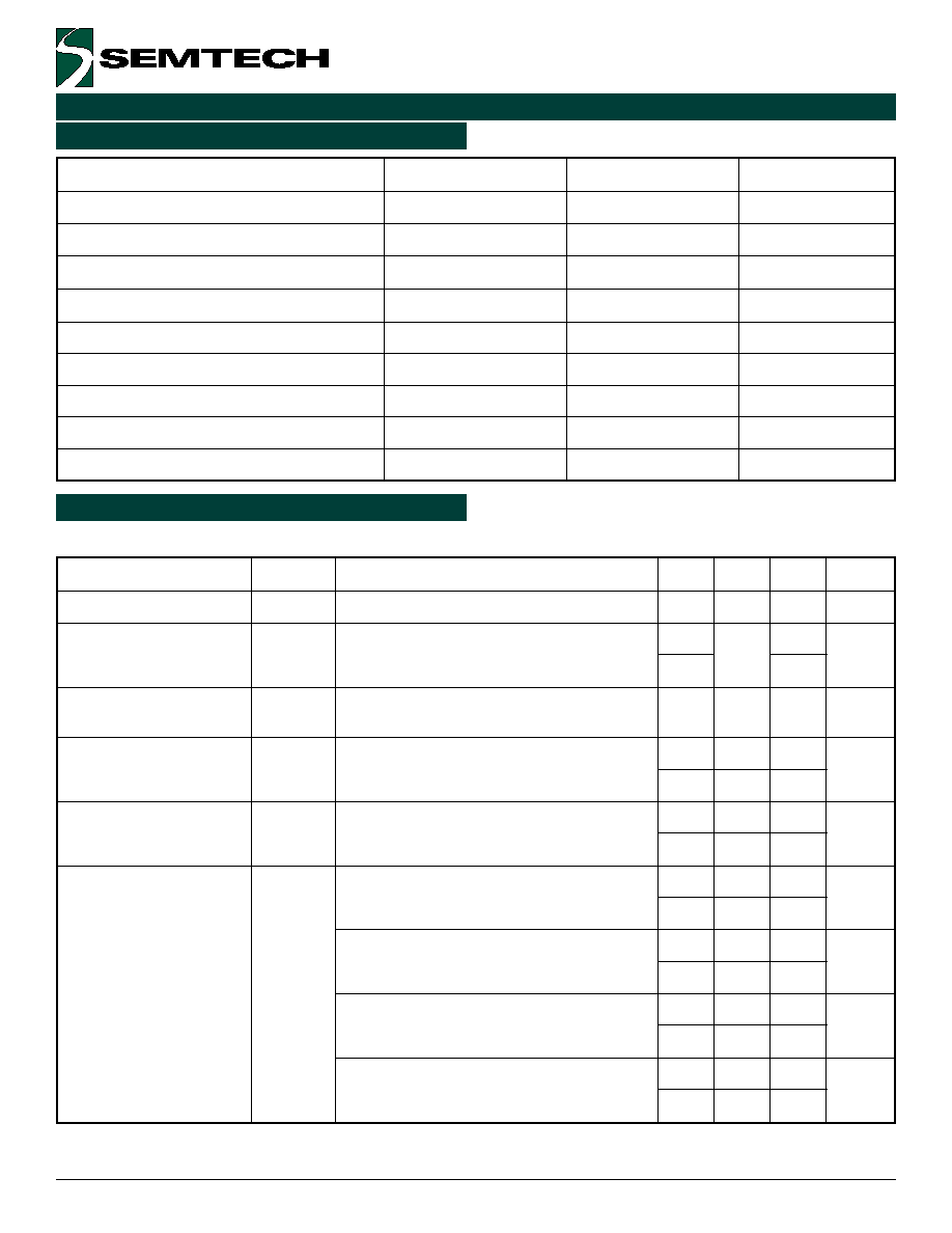
Ultra low dropout voltage - 165mV @ 150mA
u
Guaranteed 150mA output current
u
Low ground pin current at all loads
u
<5µA quiescent current in shutdown
u
Wide input supply voltage range 2.5V to 16V in
u
Wide output voltage range
u
Excellent line regulation
u
Industrial temperature range
u
Surface mount packaging (5 pin SOT-23)
u
Battery Powered Systems
u
Cellular Telephones
u
Cordless Telephones
u
Pagers
u
Personal Digital Assistants
u
Portable Instrumentation
u
Cameras
u
Portable Consumer Equipment
u
PCMCIA cards
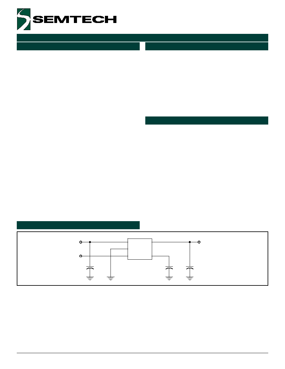
EN
VIN
VO
+
C1
1uF
U1
SC5205
1
2
3
4
5
VIN
GND
EN
BYP
VO
+
C3
1uF
C2
10nF
Description
Features
Applications
Typical Application Circuit
Notes:
(1) C
IN
(C1) is needed if the device is far from the supplys filter capacitors, or for operation from a battery. A value
of 1.0µF or greater should be used. C
IN
may be tantalum or aluminum electrolytic.
(2) C
O
(C3) should be a 1µF or greater tantalum or aluminum electrolytic capacitor. Larger value capacitors will
improve the overall transient response.
(3) C
BYP
(C2 - required) should be placed as close as possible to pin 4 and ground. A 10nF ceramic capacitor is
recommended.
(4) EN may be tied to V
IN
if the shutdown feature is not required. Maximum EN voltage = V
IN
.