
1
United States Patents: 6,504,422, 6,794,926
www.semtech.com
POWER MANAGEMENT
OBJECTIVE -NOVEMBER
9, 2000
SC604A
Low Noise, High Efficiency
Regulated White LED Driver
Features
April 28, 2005
Description
Applications
Typical Application Circuit
The SC604A is a very high efficiency charge pump white
LED driver driver from the mAhXLife
TM
family of products,
optimized for Li-Ion battery applications.
The four (4) LED outputs are current matched for consis-
tent LED brightness. Extremely low battery current is
achieved by automatically reconfiguring the charge pump
to match circuit conditions. Using four LEDs, each at
20mA for a total I
OUT
= 80mA, the SC604A can use less
than 83mA from the supply for most of the battery life.
Patented low noise mode switching circuitry and constant
output current allow the use of extremely small input and
output capacitors.
Very high efficiency over 90% of battery life
Peak efficiency over 92%
Current regulation for up to 4 LEDs
Digital 3 bit output control logic
Current matching tolerance of �3% typical
Wide current range per LED [0.5mA - 30mA]
High available total LED current = 4
I
LED
= 120mA
Low Shutdown Current: 1�A typical
Soft start / In-rush current limiting
Short circuit protection
MLP-16 [4x4] Package
Fixed frequency 250kHz
1x, 1.5x and 2x charge pump modes of operation
Cellular phones
LED backlighting
PDA power supplies
Portable devices
Electronic books
Wireless web appliances
LCD Modules
Patent Pending
VIN
EN
CTRL0
CTRL1
BATTERY
1
�F
CTRL2
GND
ILED1
ILED2
ILED3
ILED4
VOUT
C1+
C1-
C2+
C2-
SC604A
1
�F
1
�F
1
�F
ISET
2
2005 Semtech Corp.
www.semtech.com
SC604A
POWER MANAGEMENT
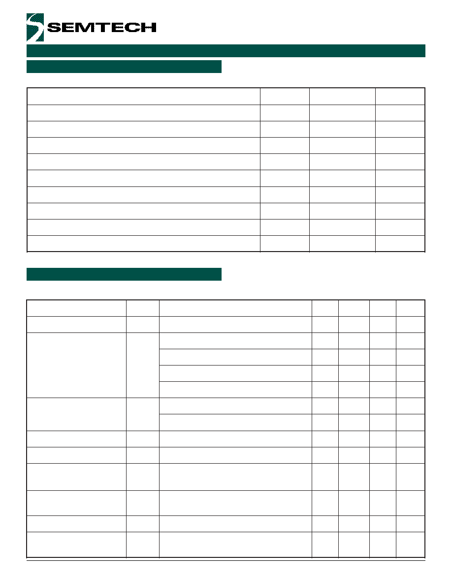
Absolute Maximum Ratings
Electrical Characteristics
r
e
t
e
m
a
r
a
P
l
o
b
m
y
S
m
u
m
i
x
a
M
s
t
i
n
U
e
g
a
tl
o
V
y
l
p
p
u
S
N
I
V
0
.
7
+
o
t
3
.
0
-
V
e
g
a
tl
o
V
t
u
p
t
u
O
V
T
U
O
0
.
7
+
o
t
3
.
0
-
V
V
T
U
O
n
o
it
a
r
u
D
ti
u
c
r
i
C
t
r
o
h
S
C
S
e
ti
n
if
e
d
n
I
s
t
n
e
i
b
m
A
o
t
n
o
it
c
n
u
J
,
e
c
n
a
t
s
i
s
e
R
l
a
m
r
e
h
T
)
1
(
A
J
0
4
W
/
C
�
t
n
e
i
b
m
A
g
n
it
a
r
e
p
O
T
A
5
8
+
o
t
0
4
-
C
�
e
g
n
a
R
e
r
u
t
a
r
e
p
m
e
T
n
o
it
c
n
u
J
T
J
0
5
1
+
o
t
0
4
-
C
�
e
g
n
a
R
e
r
u
t
a
r
e
p
m
e
T
e
g
a
r
o
t
S
T
G
T
S
0
5
1
+
o
t
5
6
-
C
�
R
T
L
M
I
A
4
0
6
C
S
e
r
u
t
a
r
e
p
m
e
T
w
o
lf
e
R
R
I
T
D
A
E
L
0
4
2
C
�
T
R
T
L
M
I
A
4
0
6
C
S
e
r
u
t
a
r
e
p
m
e
T
w
o
lf
e
R
R
I
T
D
A
E
L
0
6
2
C
�
r
e
t
e
m
a
r
a
P
l
o
b
m
y
S
s
n
o
i
t
i
d
n
o
C
n
i
M
p
y
T
x
a
M
s
t
i
n
U
e
g
a
tl
o
V
y
l
p
p
u
S
t
u
p
n
I
N
I
V
5
.
2
5
.
6
V
s
D
E
L
o
t
n
i
t
n
e
r
r
u
C
4
d
n
a
3
,
2
,
1
I
D
E
L
R
T
E
S
k
0
.
4
2
=
0
2
A
m
R
T
E
S
k
0
.
4
9
=
0
.
5
A
m
V
7
.
2
< N
I
V
<
V
5
.
5
5
.
0
0
2
A
m
V
1
.
3
< N
I
V
<
V
5
.
5
5
.
0
0
3
A
m
t
n
e
r
r
u
C
t
n
e
c
s
e
i
u
Q
I
Q
I
T
U
O
A
m
5
=
0
0
5
1
0
0
0
2
�A
V
0
=
e
l
b
a
n
E
1
7
�A
I
D
E
L
y
c
a
r
u
c
c
A
I
R
R
E
-
D
E
L
A
m
5
.
0
I
D
E
L
A
m
0
3
5
�
%
g
n
i
h
c
t
a
M
t
n
e
r
r
u
C
I
R
R
E
-
D
E
L
-
D
E
L
A
m
5
.
0
I
D
E
L
A
m
0
3
3
�
%
e
d
o
m
x
5
.
1
o
t
e
d
o
m
x
1
V
(
e
g
a
tl
o
v
n
o
it
i
s
n
a
r
t
N
I
)
g
n
il
l
a
f
V
X
1
S
N
A
R
T
V
D
E
L
I
,
V
6
.
3
=
T
U
O
I
,
A
m
0
8
=
D
E
L
A
m
0
2
=
6
9
7
.
3
V
e
d
o
m
x
2
o
t
e
d
o
m
x
5
.
1
V
(
e
g
a
tl
o
v
n
o
it
i
s
n
a
r
t
N
I
)
g
n
il
l
a
f
V
X
5
.
1
S
N
A
R
T
V
D
E
L
I
,
V
6
.
3
=
T
U
O
I
,
A
m
0
8
=
D
E
L
A
m
0
2
=
0
2
3
.
3
V
y
c
n
e
u
q
e
r
F
r
o
t
a
ll
i
c
s
O
f
C
S
O
5
.
2
1
2
0
5
2
5
.
7
8
2
z
H
k
e
g
a
tl
o
V
r
e
v
O
t
u
p
t
u
O
n
o
it
c
e
t
o
r
P
)
1
(
V
P
V
O
s
i
t
a
h
t
D
E
L
y
n
a
t
a
ti
u
c
r
i
c
n
e
p
O
e
t
a
t
s
n
O
e
h
t
n
i
e
b
o
t
d
e
m
m
a
r
g
o
r
p
0
.
5
V
Unless specified: T
A
= -40�C to 85�C, V
IN
= 2.85V to 5.5V, C1 = C2 = 1.0
�
F (ESR = 0.03
). Typical values @ T
A
=25�C, LED V
F
= 3.4V.
This device is ESD sensitive. Use of standard ESD handling precautions is required.
Note: (1) By JESD51 standards
Exceeding the specifications below may result in permanent damage to the device, or device malfunction. Operation outside of the parameters
specified in the Electrical Characteristics section is not implied.

3
2005 Semtech Corp.
www.semtech.com
SC604A
POWER MANAGEMENT
Electrical Characteristics (Cont.)
r
e
t
e
m
a
r
a
P
l
o
b
m
y
S
s
n
o
i
t
i
d
n
o
C
n
i
M
p
y
T
x
a
M
s
t
i
n
U
ti
m
i
L
t
n
e
r
r
u
C
t
u
p
n
I
T
I
M
I
L
I
D
N
G
o
t
T
U
O
V
m
o
r
f
d
e
il
p
p
a
ti
u
c
r
i
c
t
r
o
h
S
0
2
2
0
5
8
A
m
d
l
o
h
s
e
r
h
T
h
g
i
H
t
u
p
n
I
V
H
I
d
l
o
h
s
e
r
h
t
c
i
g
o
l
h
g
i
h
t
u
p
n
I
3
.
1
V
d
l
o
h
s
e
r
h
T
w
o
L
t
u
p
n
I
V
L
I
d
l
o
h
s
e
r
h
t
c
i
g
o
l
w
o
l
t
u
p
n
I
4
.
0
V
t
n
e
r
r
u
C
h
g
i
H
t
u
p
n
I
I
H
I
V
H
I
V
=
N
I
0
1
�
A
t
n
e
r
r
u
c
w
o
L
t
u
p
n
I
I
L
I
V
L
I
D
N
G
=
0
1
�
A
Notes:
(1) Guaranteed by design
Unless specified: T
A
= -40�C to 85�C, V
IN
= 2.85V to 5.5V, C1 = C2 = 1.0
�
F (ESR = 0.03
). Typical values @ T
A
=25�C, LED V
F
= 3.4V.

4
2005 Semtech Corp.
www.semtech.com
SC604A
POWER MANAGEMENT
Definitions
I
LED
Accuracy
The LED current is determined by the R
SET
resistor (I
LED
vs. R
SET
data is found on pages 9 and 10). This term
does not include the tolerance of the resistor R
SET
. If
maximum accuracy is required, a precision resistor is
needed. To calculate the error I
LED-ERR
[%], use the formula
I
LED-ERR
[%] = �
Current Matching
Current Matching refers to the difference in current from
one LED to the next. The
I between any two LEDs will
meet this requirement. To calculate the error I
LED-LED-ERR
,
first identify the highest and lowest value of the 4 LED
currents, and use the formula:
I
LED-LED-ERR
[%] =
or
which reduces to �
1x Mode, 1.5x Mode and 2x Mode
1x Mode, 1.5x Mode and 2x Mode all refer to the charge
pump configuration. These modes boost the battery input
voltage and ensure there is enough voltage at V
OUT
so
that the regulated current will flow through the LEDs and
return via the I
LED
pins.
I
LED
( )
MEASURED
I LED
-
I LED
%
100
I
MAX
I
MAX
+ I
MIN
- 1
100%
2
I
MIN
I
MAX
+ I
MIN
- 1
100%
2
I
MIN
100%
I
MAX
I
MIN
I
MAX
+
Input Current
The total input current of the SC604A is a function of
the sum of the LED currents, the charge pump mode
and the quiescent current. The quiescent current trend
is charted on page 12 and used to calculate I
IN
in the
following examples.
I
IN
= I
OUT
Mode + I
Q
=
(I
LED1
+I
LED2
+I
LED3
+I
LED4
)
Mode + I
Q
Example 1:
Mode = 1x, I
Q
= 2.4mA,
I
LED1
+I
LED2
+I
LED3
+I
LED4
= 4
15mA = 60mA
Answer 1:
I
IN
= I
OUT
Mode + I
Q
= 60mA
1 + 2.4mA =
62.4mA
Example 2:
Mode = 1.5x, I
Q
= 2.4mA,
I
LED1
+I
LED2
+I
LED3
+I
LED4
= 4
15mA = 60mA
Answer 2:
I
IN
= I
OUT
Mode + I
Q
= 60mA
1.5 + 2.4mA =
92.4mA
Mode Transition Voltage
Mode transition voltage refers to the input voltage at
the point just before the charge pump changes from a
weaker mode to a stronger mode. V
TRANS1X
is the
transition from 1x to 1.5x mode, and V
TRANS1.5X
is the
transition from 1.5x to 2x mode. Equations for V
TRANS1X
and V
TRANS1.5X
are given on page 7.

5
2005 Semtech Corp.
www.semtech.com
SC604A
POWER MANAGEMENT
n
i
P
e
m
a
N
n
i
P
n
o
i
t
c
n
u
F
n
i
P
1
N
E
e
l
b
a
n
e
h
g
i
h
e
v
it
c
A
2
0
L
R
T
C
)
6
e
g
a
p
n
o
1
e
l
b
a
T
e
e
s
(
0
ti
b
l
o
r
t
n
o
c
t
u
p
t
u
O
3
1
L
R
T
C
)
6
e
g
a
p
n
o
1
e
l
b
a
T
e
e
s
(
1
ti
b
l
o
r
t
n
o
c
t
u
p
t
u
O
4
2
L
R
T
C
)
6
e
g
a
p
n
o
1
e
l
b
a
T
e
e
s
(
2
ti
b
l
o
r
t
n
o
c
t
u
p
t
u
O
5
T
E
S
I
R
r
o
t
s
i
s
e
r
e
h
t
f
o
e
u
l
a
v
e
h
t
y
b
t
e
s
s
i
t
n
e
r
r
u
c
D
E
L
T
E
S
t
o
n
o
D
.
d
n
u
o
r
g
o
t
n
i
p
T
E
S
I
e
h
t
m
o
r
f
d
e
t
c
e
n
n
o
c
V
.
n
i
p
T
E
S
I
e
h
t
t
r
o
h
s
T
E
S
I
V
2
2
.
1
y
ll
a
c
i
p
y
t
s
i
6
T
U
O
V
s
e
d
o
n
a
D
E
L
e
h
t
o
t
n
o
it
c
e
n
n
o
c
r
o
f
e
c
r
u
o
s
t
u
p
t
u
o
e
g
a
tl
o
V
7
N
I
V
t
u
p
n
i
e
g
a
tl
o
V
8
+
1
C
1
r
o
ti
c
a
p
a
c
t
e
k
c
u
b
f
o
l
a
n
i
m
r
e
t
e
v
it
i
s
o
P
9
-
1
C
1
r
o
ti
c
a
p
a
c
t
e
k
c
u
b
f
o
l
a
n
i
m
r
e
t
e
v
it
a
g
e
N
0
1
-
2
C
2
r
o
ti
c
a
p
a
c
t
e
k
c
u
b
f
o
l
a
n
i
m
r
e
t
e
v
it
a
g
e
N
1
1
+
2
C
2
r
o
ti
c
a
p
a
c
t
e
k
c
u
b
f
o
l
a
n
i
m
r
e
t
e
v
it
i
s
o
P
2
1
D
N
G
d
n
u
o
r
G
3
1
4
D
E
L
I
V
o
t
d
e
t
c
e
n
n
o
c
r
o
,
d
e
d
n
u
o
r
g
,
n
e
p
o
t
f
e
l
e
b
y
a
m
n
i
p
,
e
s
u
n
i
t
o
n
fl
[
4
D
E
L
r
o
f
k
n
i
s
t
n
e
r
r
u
C
N
I
]
)
1
(
4
1
3
D
E
L
I
V
o
t
d
e
t
c
e
n
n
o
c
r
o
,
d
e
d
n
u
o
r
g
,
n
e
p
o
t
f
e
l
e
b
y
a
m
n
i
p
,
e
s
u
n
i
t
o
n
fl
[
3
D
E
L
r
o
f
k
n
i
s
t
n
e
r
r
u
C
N
I
]
)
1
(
5
1
2
D
E
L
I
V
o
t
d
e
t
c
e
n
n
o
c
r
o
,
d
e
d
n
u
o
r
g
,
n
e
p
o
t
f
e
l
e
b
y
a
m
n
i
p
,
e
s
u
n
i
t
o
n
fl
[
2
D
E
L
r
o
f
k
n
i
s
t
n
e
r
r
u
C
N
I
]
)
1
(
6
1
1
D
E
L
I
V
o
t
d
e
t
c
e
n
n
o
c
r
o
,
d
e
d
n
u
o
r
g
,
n
e
p
o
t
f
e
l
e
b
y
a
m
n
i
p
,
e
s
u
n
i
t
o
n
fl
[
1
D
E
L
r
o
f
k
n
i
s
t
n
e
r
r
u
C
N
I
]
)
1
(
T
d
a
P
l
a
m
r
e
h
T
y
ll
a
n
r
e
t
n
I
d
e
t
c
e
n
n
o
c
t
o
N
.
s
a
i
v
e
l
p
it
l
u
m
g
n
i
s
u
e
n
a
l
p
d
n
u
o
r
g
o
t
t
c
e
n
n
o
C
.
s
e
s
o
p
r
u
p
g
n
i
k
n
i
s
t
a
e
h
r
o
f
d
a
P
Pin Descriptions
E
C
I
V
E
D
E
G
A
K
C
A
P
)
1
(
R
T
L
M
I
A
4
0
6
C
S
6
1
-
P
L
M
T
R
T
L
M
I
A
4
0
6
C
S
)
2
(
6
1
-
P
L
M
B
V
E
4
0
6
C
S
d
r
a
o
B
n
o
it
a
u
l
a
v
E
Notes:
(1) Available in tape and reel only. A reel contains 3000 devices.
(2) Available in lead-free package only. This product is fully WEEE and
RoHS compliant.
Ordering Information
Pin Configuration
Note: (1) The CTRL word must match the outputs in use.
TOP VIEW
MLPQ16: 4X4 16 LEAD
ISET VOUT VIN C1+
ILED1 ILED2 ILED3 ILED4
EN
CTRL0
CTRL1
CTRL2
GND
C2+
C2-
C1-
TOP VIEW
1
2
3
4
12
11
10
9
16
15
14
13
5
6
7
8
T