www.semtech.com
POWER MANAGEMENT
SC635
Charge Pump
Flash LED Driver
u
Twoselectablemodes-FlashandSpotlight
u
200mAmaxoutput-FlashMode
u
Spotlightmodesetto40%ofFlashCurrent
u
3.0Vto5.25VInputRange
u
Externalpinsforcontrolofflashandspotlightmodes
forsynchronizationtoacameramoduleorgraphics
controller
u
Shortcircuit,over-voltage,andover-temperature
protection
u
Soft-startfunctionality
u
MicroLeadPackageMLPD-0,3mmx3mm
December2,2005
Description
Features
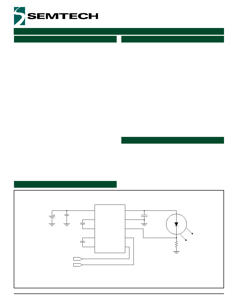
TypicalApplicationCircuit
TheSC635isahigh-currentchargepumpdesignedspe-
cificallyforusewithwhiteLEDsusedincameraflashap-
plications.Onlytwosmallbucketcapacitorsarerequired
todeveloptheoutputdrive,providingalowEMIsolution
comparedtoinductiveboostregulators.
TheSC635hastwomodesofoperation:Flashmodeand
Spotlightmode.InFlashmode,theSC635iscapableof
delivering 200mA to a high-intensity LED during image
capture.InSpotlightmodetheSC635outputs40%ofthe
Flashmodecurrentforgeneralpurposelightingorstatus
indication.
AnexternalresistorisconnectedinserieswiththeLEDto
setthecurrent.InFlashmode,thisresistorcandissipate
upto50mW,reducingthepowerdissipationrequirement
oftheSC635.Theflashinput(FLASH)overridesthecon-
trolinput(CTRL)tomakesuretheflashfunctionisacti-
vatedwhencalledfor.
ThethermallyefficientMLPD-10packageandceramicby-
passandbucketcapacitorsmaketheSC635ahighout-
putcurrentdriverthatrequiresminimalPCBarea.
u
MobileCameraPhones
u
DigitalCameras
u
PDAswithBuilt-inCameras
VBAT
SC635
VIN
1
C2-
2
C2+
10
C1-
4
C1+
8
VOUT
9
FLASH
5
CTRL
7
GND
3
ISET
6
1�F
1�F
FLASH
CTRL
1�F
white LED
RSET
10�F
TypicalApplicationCircuit
Applications
Features
2
2005SemtechCorp.
www.semtech.com
POWER MANAGEMENT
SC635
AbsoluteMaximumRatings
Exceedingthespecificationsbelowmayresultinpermanentdamagetothedeviceordevicemalfunction.Operationoutsideoftheparametersspecifiedinthe
ElectricalCharacteristicssectionisnotimplied.
Unlessotherwisespecified:TA=25�CforTYP,-40�Cto+60�CforMINandMAX;
C
BUCKET
=C
OUT
=1.0F(ESR<0.1);C
IN
=10.0F;V
VIN
=3.0Vto5.25V;V
VOUT
=2.8Vto4.25V;R
SET
=0.5(0.1%).
(1)Calculatedfrompackageinstillair,mountedto3"x4.5",4layerFR4PCBwiththermalviasundertheexposedpadasperJESD51standards.
(2)TestedaccordingtoJEDECstandardJESD22-A114-B.
Parameter
Symbol
Maximum
Units
Input Supply Voltage
V
VIN
-0.3 to +6.5
V
Output Voltage
V
VOUT
-0.3 to +6.5
V
Pin Voltage - FLASH, CTRL, ISET, C1-, C2-
-0.3 to V
VIN
+ 0.3
V
Pin Voltage - C1+, C2+
-0.3 to V
VOUT
+ 0.3
V
Thermal Resistance, Junction to Ambient
(JESD51 Standard Method)
(1)
q
JA
49
�C/W
VOUT Short Circuit Duration
SC
Indefinite
s
Operating Ambient Temperature Range
T
A
-40 to +85
�C
Junction Temperature Range
T
J
-40 to +150
�C
Storage Temperature Range
T
STG
-60 to +150
�C
Peak IR Flow Temperature
T
LEAD
260
�C
ESD Protection Level
(2)
V
ESD
2
kV
Parameter
Symbol
Conditions
Min
Typ
Max
Units
Output Current
I
OUT
FLASH high, R
ISET
= 1.25W
3.3V < V
VIN
< 4.2V
2.8V < V
VOUT
= 4.25V
184
200
216
mA
FLASH low, CTRL high, R
ISET
= 1.25W
3.0V < V
VIN
< 4.5V
2.8V < V
VOUT
< 4.5V
68
80
92
ISET Reference Voltage
V
ISET
FLASH high, R
ISET
= 1.25W
3.3V < V
VIN
< 4.2V
2.8V < V
VOUT
< 4.25V
230
250
270
mV
FLASH low, CTRL high, R
ISET
= 1.25W
3.0V < V
VIN
< 4.5V
2.8V < V
VOUT
< 4.5V
85
100
115
Quiescent Current
I
Q
FLASH high
3.4
5.0
mA
FLASH low, CTRL high
2.0
4.5
mA
FLASH low, CTRL low
0.1
2.0
�A
AbsoluteMaximumRatings
ElectricalCharacteristics
3
2005SemtechCorp.
www.semtech.com
POWER MANAGEMENT
SC635
Parameter
Symbol
Conditions
Min
Typ
Max
Units
Flash Mode Start-up Time
(1)
t
F-SU
t = 0 when FLASH goes high to I
OUT
= 90%
of final value
1
ms
Flash Mode Pulse Duration
t
FLASH
3.3V < V
VIN
< 4.2V
I
OUT
= 200mA, V
VOUT
> 2.8V
indefinite
s
Spotlight Mode Start-up Time
(1)
t
S-SU
t = 0 when CTRL goes high to I
OUT
= 90%
of final value
1
ms
Oscillator Frequency
f
OSC
Device enabled
250
kHz
Oscillator Frequency Accuracy
D
f
OSC
-15
15
%
Short-circuit Output Current
Limit
I
SC
VOUT shorted to GND
465
mA
Input Current Limit
I
LIMIT
3.3V < V
VIN
< 4.2V
1.0
2.1
A
Over-temperature Protection
(1)
T
OT
150
�C
Hysteresis
10
Logic Input High Threshold
V
IH
FLASH, CTRL
1.5
V
Logic Input Low Threshold
V
IL
FLASH, CTRL
0.4
V
Logic Input High Current
I
IH
FLASH
1
20
35
�A
CTRL
2
40
70
Logic Input High Current
I
IL
FLASH, CTRL
0.1
2.0
�A
ISET Ripple Voltage
(1)
V
ISET(P-P)
Spotlight mode - I
OUT
= 80mA
25
mV
FLASH mode - I
OUT
= 200mA
100
Notes:
(1)Guaranteedbydesign-nottestedinproduction.
ElectricalCharacteristics(Cont.)
4
2005SemtechCorp.
www.semtech.com
POWER MANAGEMENT
SC635
DEVICE
PACKAGE
(1)
SC635MLTRT
(2)(1)
(1)(2)
MLPD-10 3x3
SC635EVB
Evaluation Board
Notes:
(1) Available in tape and reel only. A reel contains 3,000 devices.
(2) Available in lead-free package only. Device is WEEE and
RoHS compliant.
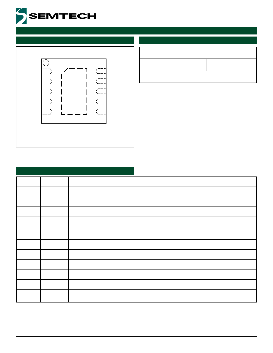
Pin#
Pin Name Pin Function
1
VIN
Input voltage.
2
C2-
Negative terminal of bucket capacitor 2.
3
GND
Ground - connect to ground plane using multiple vias.
4
C1-
Negative terminal of bucket capacitor 1.
5
FLASH
Flash mode enable pin - puts the device in active Flash mode when high and also overrides
CTRL.
6
ISET
Current-setting reference pin - connect to the LED cathode and the current setting resistor.
7
CTRL
Control input bit - used to enable and set the output current in Spotlight mode when high.
8
C1+
Positive terminal of bucket capacitor 1.
9
VOUT
Output pin.
10
C2+
Positive terminal of bucket capacitor 2.
T
Thermal
Pad
Pad for heat sinking purposes - not connected internally. Connect to ground plane using
multiple vias.
PinConfiguration
OrderingInformation
PinDescriptions
TOPVIEW
1
2
3
4
10
9
8
7
5
6
MLP10:3X310LEAD
T
VIN
C2-
GND
C1-
FLASH
C2+
VOUT
C1+
CTRL
ISET

5
2005SemtechCorp.
www.semtech.com
POWER MANAGEMENT
SC635
PinConfiguration
ApplicationsInformation
GeneralOperation
The SC635 is a powerful 2X charge pump designed to
driveahigh-intensitywhiteLEDwithaconstantcurrent
(Spotlightmode)orwithapulsedcurrentofhigherinten-
sity(Flashmode)usedforcameraflash.
In Flash mode the SC635 output can drive 200mA at
4.25V into an LED for an unlimited duration under all
temperatureandinputconditions.TheFLASHpinisused
totriggerthismode(activehigh).InSpotlightmodethe
SC635regulatestheoutputcurrentto40%oftheFlash
mode current setting when the CTRL pin is pulled high
andtheFLASHpinislow.NotethatFlashmodehasprior-
ityoverSpotlightmode,i.e.,theFLASHpintriggersFlash
moderegardlessofthestateoftheCTRLpin.
OutputcurrentisregulatedbyattachingtheISETpinto
thecathode(s)oftheLEDpackageandalowresistance
sense resistor (typically 1.25). The ISET pin monitors
thevoltageatthecathodeandsignalsthechargepump
toincreaseordecreasetheoutputcurrentuntiltheISET
voltage reaches the programmed setting. The resistor
valueischosentosetthecurrentthroughtheLEDbased
onthisreferencevoltage.
FlashMode
FlashmodeisenabledwhenevertheFLASHpinispulled
highandremainsactiveuntiltheFLASHpinisreleased.
ThismodehashigherprioritythanSpotlightmode,sothe
stateoftheCTRLpinisoverriddenwhenevertheFLASH
pinisactivated.WhileinFlashmodethereferencevolt-
ageontheISETpinissetto250mV.
Outputcurrentsotherthantheratedmaximumof200mA
canbesetbychangingtheR
ISET
value.InFlashmode,
IOUT=250mV/R
ISET
.
SpotlightMode
SpotlightmodeisenabledbysettingtheCTRLpinhigh
andkeepingtheFLASHpinlow.WheninSpotlightmode,
theSC635canmaintainaconstantcurrentindefinitelyto
driveanLEDorbankofLEDs.TheISETreferencevoltage
issetto00mVsothattheoutputcurrentismaintained
at80mAwhena1.25resistorisused.Spotlightcurrent
isalways40%offlashcurrentforanygivenvalueofR
ISET
.
Inspotlightmode,IOUT=100mV/R
ISET
.Theresistorval-
ueshouldnotexceed2,however,toensuretheSC635
doesnotbecomeunstablewhileinSpotlightmodedueto
theoutputcurrentbeingsettoolow.
ProtectionCircuitry
TheSC635alsoprovidesprotectioncircuitrythatprevents
thedevicefromoperatinginanunspecifiedstate.These
functions include Input Over-Voltage Protection (IOVP),
Output Over-Voltage Protection (OVP), Over-Temperature
(OT)Protection,Over-CurrentProtection(OCP),andShort-
CircuitCurrentProtection(SCCP).
Input Over-Voltage Protection
Inputover-voltageprotectionisincludedtopreventopera-
tionathighinputvoltagesthatcoulddamagethedevice.
TheIOVPcircuitsensestheinputvoltageanddetermines
whenthesupplyexceeds6V.Hysteresisisincludedinthis
circuittoavoidchatteringbetweenstates.Whenthevolt-
agerisesabovethisthreshold,thedeviceisdisabledun-
tiltheinputvoltagedropstoalevelwithinthespecified
range.
Output Over-Voltage Protection
Outputover-voltageprotectionisincludedtopreventthe
SC635fromgeneratinganoutputvoltagethatcoulddam-
ageotherdevicesconnectedtoitsuchasloadLEDsand
bypasscapacitors.Whentheoutputvoltageexceeds5.5V,
theOVPcircuitdisablesthechargepumpuntilthevoltage
decreases to a level within the acceptable range. This
circuitallowsthedevicetodriveLEDswithhighforward
voltagesatareducedlevelwithoutexceedingtheoutput
voltagelimitsspecifiedforthedevice.Note,however,that
thiseffectisaconsequenceoftheOVPcircuitandisnot
itsintendedpurpose.
Over-Temperature Protection
The over-temperature circuit helps prevent the device
from overheating and experiencing a catastrophic fail-
ure.Whenthejunctiontemperatureexceeds150�Cthe
deviceisdisabled.Itremainsdisableduntilthejunction
temperaturedropsbelowthisthreshold.AswiththeUVLO
andOVPcircuits,hysteresisisincludedtopreventtoggling
betweenmodes.
Over-Current Protection
When the SC635 is in 2X mode, the input current will
beapproximatelydoubletherequiredoutput.Whenthe
steady-stateloadrequiresthemaximumcurrentavailable
in2Xmode,theOCPcircuitpreventsthedevicefromover-
heatingduetoexcessivepowerdissipation.

6
2005SemtechCorp.
www.semtech.com
POWER MANAGEMENT
SC635
Short-Circuit Current Protection
Short-circuitcurrentprotectionisprovidedtolimitthecur-
rentthatcanbesourcedwhentheoutputisshortedto
ground.WhenashortcircuitforcesVOUTtodropbelow
2V,theSCCPdetectstheconditionandlimitstheoutput
current.
ResistorSelection
TheISETresistorselectioniscriticalingeneratingthecor-
rectcurrent.ThevaluecanbechosentosettheSpotlight
modecurrentortheFlashmodecurrent,butitmustbe
notedthatthetwocurrentsettingsaredependentonthe
sameresistance.Itisrecommendedthattheresistorbe
selectedtomatchthedesiredLEDcurrentforFlashmode.
ThisallowsthedesignertosettheSC635'smaximumcur-
rent and select the resistor package size necessary for
thepowerdissipationrequiredinFlashmode.Thetypical
applicationshownonpage1usesa1.25resistortoset
aflashmodecurrentof200mAandspotlightmodecur-
rentof80mA.Ahighprecisionresistorshouldbeusedto
ensurethespecifiedaccuracyforLEDcurrent.
To avoid malfunction of the charge pump, it is recom-
mendedthattheresistanceseenattheISETpinremain
constant while the device is active (Flash or Spotlight
mode). Changing the resistance value or the load cur-
rentwhilethedeviceisactivecouldcauseinstabilitythat
wouldresultinnon-compliantbehavior.
TheloadcurrentreturnpathisfromtheISETsensepoint
throughtheresistorandbacktothegroundpins.Resis-
tanceinthispathaddstothetotalresistanceandhasthe
effectofreducingtheLEDcurrentbyabout4%per0mV
ApplicationsInformation(Cont.)
ofDCdropacrossthereturncoppertraceinflashmode.
Forthisreason,itiscrucialtohavealowresistancereturn
path.Placeandgroundtheresistorascloseaspossible
tothegroundpinoftheSC635.ThetracefromtheISET
pinhasvirtuallynocurrent.TheISETtraceshouldmake
contactatthepadofthepowersenseresistortominimize
theeffectofvoltagedropbetweentheLEDcathodeand
theresistor.
CapacitorSelection
TheSC635isdesignedtouselow-ESRceramiccapaci-
torsfortheinputandoutputbypasscapacitorsaswellas
thechargepumpbucketcapacitors.Idealperformance
isachievedwhenCisexactlyequaltoC2.Itisrecom-
mendedthatX5RorX7Rceramiccapacitorsbeusedfor
bestperformance.
ThermalResistance
TheSC635packageisthermallyefficientwhenthecircuit
boardlayoutconnectsthethermalpadthoughmultiple
viastothegroundplane.Thethermalresistanceisrated
at49�C/W,andthisratingisdependentontheconnec-
tionbetweenthethermalpadandthegroundplane.A
layoutthatisdonecorrectlyshouldkeepthejunctiontem-
perature below the OT limit while operating the SC635
withinthespecifiedelectricalconditionsforIOUTandV
ISET
.
Apoorlayoutmayallowthejunctiontemperaturetoreach
theOTlimitwhileinFlashorSpotlightmode.Itiscritical
tomaintainadequategroundplanearoundthedeviceto
maximizeheattransferandavoidover-temperatureshut-
down.
7
2005SemtechCorp.
www.semtech.com
POWER MANAGEMENT
SC635
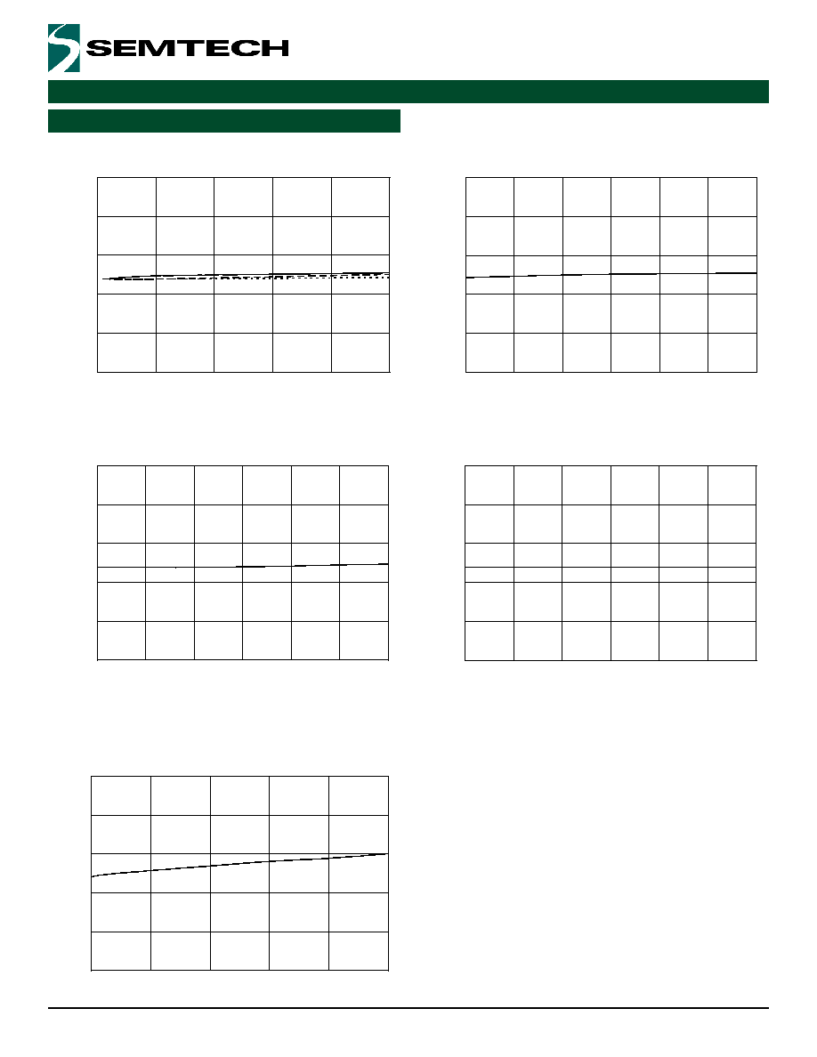
TypicalCharacteristics
80mASpotlightCurrent,RISET=1.25W,VOUT=2.96V
195.0
197.0
199.0
201.0
203.0
205.0
0
100
200
300
400
500
Pulse Duration [ms]
LED Current [mA]
VIN = 4.2V
VIN = 3.7V
VIN = 3.3V
200mAFlashDuration,RISET=1.25W,
VOUT=3.30V(start)to3.25V(LEDheated500ms)
195.0
197.0
199.0
201.0
203.0
205.0
3.3
3.45
3.6
3.75
3.9
4.05
4.2
VIN [V]
LED Current [mA]
FlashCurrentat10ms,RISET=1.25W,VOUT=3.30V
195.0
197.0
199.0
201.0
203.0
205.0
3.3
3.45
3.6
3.75
3.9
4.05
4.2
VIN [V]
LED Current [mA]
FlashCurrentat100ms,RISET=1.25W,VOUT=3.28V
195.0
197.0
199.0
201.0
203.0
205.0
3.3
3.45
3.6
3.75
3.9
4.05
4.2
VIN [V]
LED Current [mA]
FlashCurrentat500ms,RISET=1.25W,VOUT=3.25V
75.0
77.0
79.0
81.0
83.0
85.0
3
3.45
3.9
4.35
4.8
5.25
VIN [V]
LED Current [mA]
8
2005SemtechCorp.
www.semtech.com
POWER MANAGEMENT
SC635
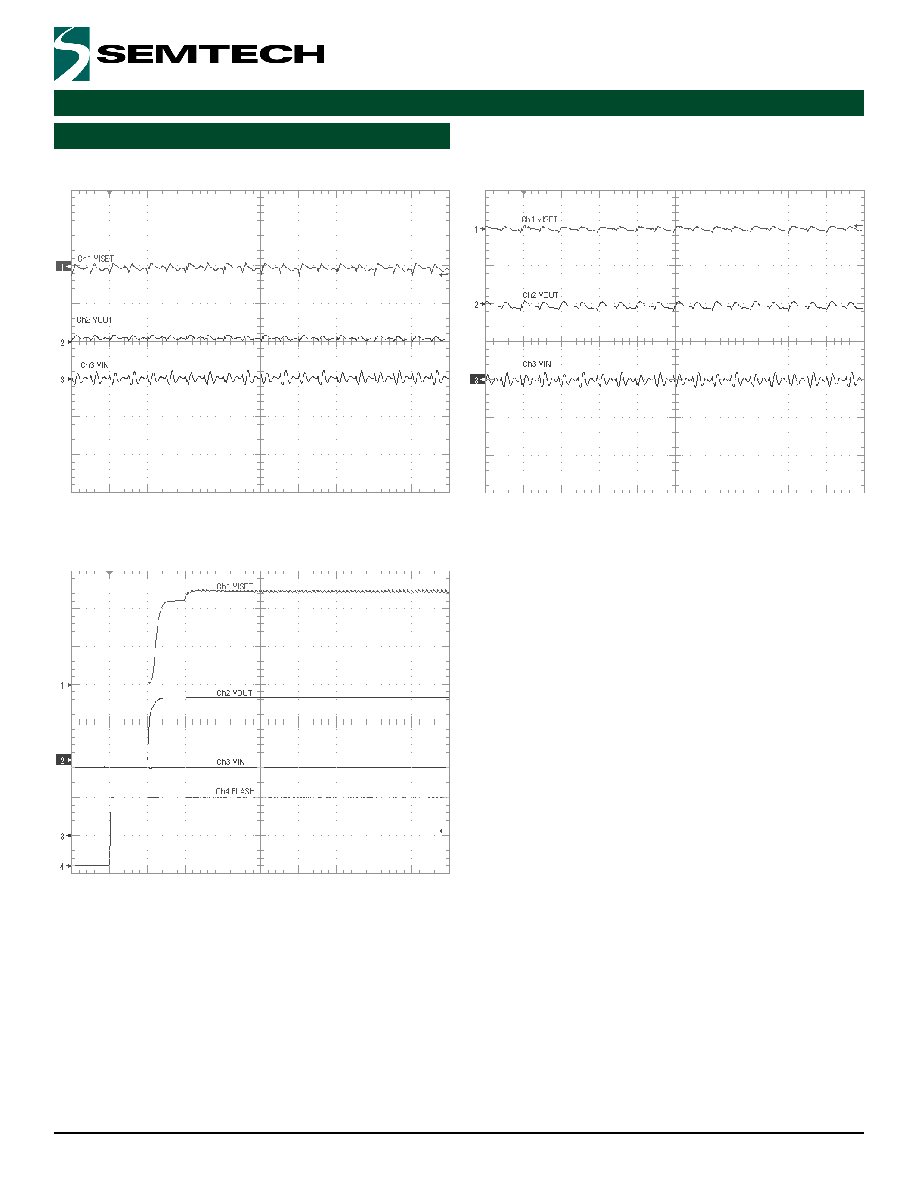
Ch150mV/div
Ch2200mV/div
Ch3200mV/div
4us/div
FlashModeRipple,RISET=1.25W
SpotlightModeRipple,RISET=1.25W
Ch150mV/div
Ch2100mV/div
Ch3100mV/div
4us/div
TypicalCharacteristics(Cont.)
StartupFlashMode200mA
Ch1100mV/div
Ch22V/div
Ch32V/div
Ch42V/div
40us/div

2005SemtechCorp.
www.semtech.com
POWER MANAGEMENT
SC635
SuggestedLayout
ThesensetracebetweenPin6andRisroutedaround
thegroundvias,allowingtheshortestgroundreturnpath
possible.ThesensetraceisconnectedtoRattheposi-
tiveterminalpadforthemostaccurateoutputpossible.
Thebottomcopperlayerismostlyagroundplanewithno
obstructionsbetweenthegroundvias.Thesmallerrect-
angletotheleftconnectstheinputpowertoVINpin1and
inputcapacitorC4.Thetwotracesatthelowerleftarefor
logicinputsFLASHandCTRL.Thetracetotherightisthe
ISETpin"sense"trace.Thesensetraceisroutedoutof
thepathofthereturninggroundcurrent.
LayoutGuidelines
Thefollowinglayoutissuggestedforatwo-layerdesign.
ThecapacitorsCandC2arethebucketcapacitorsand
eachconductsthefullloadcurrentofupto200mApulsed
foronehalfclockcycle.C3istheoutputdecouplingca-
pacitorplacedneartheSC635VOUTpin.C4isthein-
putdecouplingcapacitorplacedneartheSC635VINpin.
Multipleviasshouldbeusedwheneveritisnecessaryto
changelayersonnetsconnectingtopinsVIN,VOUT,GND,
C1-,C1+,C2-andC2+.ResistorR1isroutedwithavery
low resistance connection between R1 and GND pin 3.
BottomCopper
TopCopper
0
2005SemtechCorp.
www.semtech.com
POWER MANAGEMENT
SC635
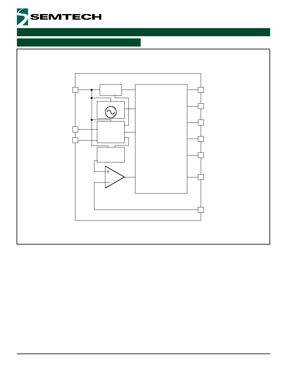
BlockDiagram
CHARGE
PUMP
250kHz
LogicControl
Reference
Voltage
Generator
LDO
C+
C-
C2+
C2-
VOUT
ISET
VIN
CTRL
FLASH
GND
8
4
10
2
9
3
6
5
7
1
2005SemtechCorp.
www.semtech.com
POWER MANAGEMENT
SC635
MarkingInformation
635
yyww
xxxx
Top Mark
yyww = Datecode (Example = 0552)
xxxx = Semtech Lot Number
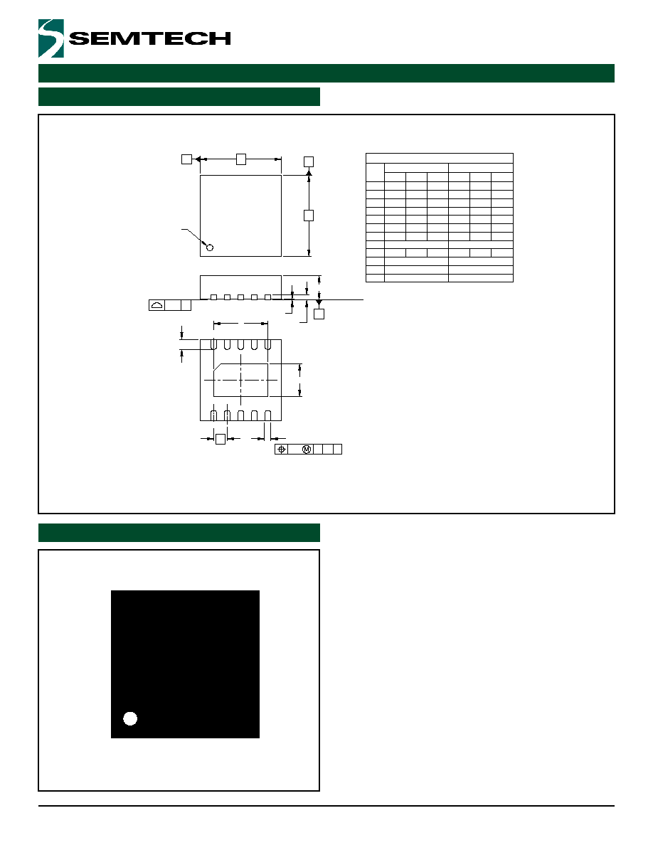
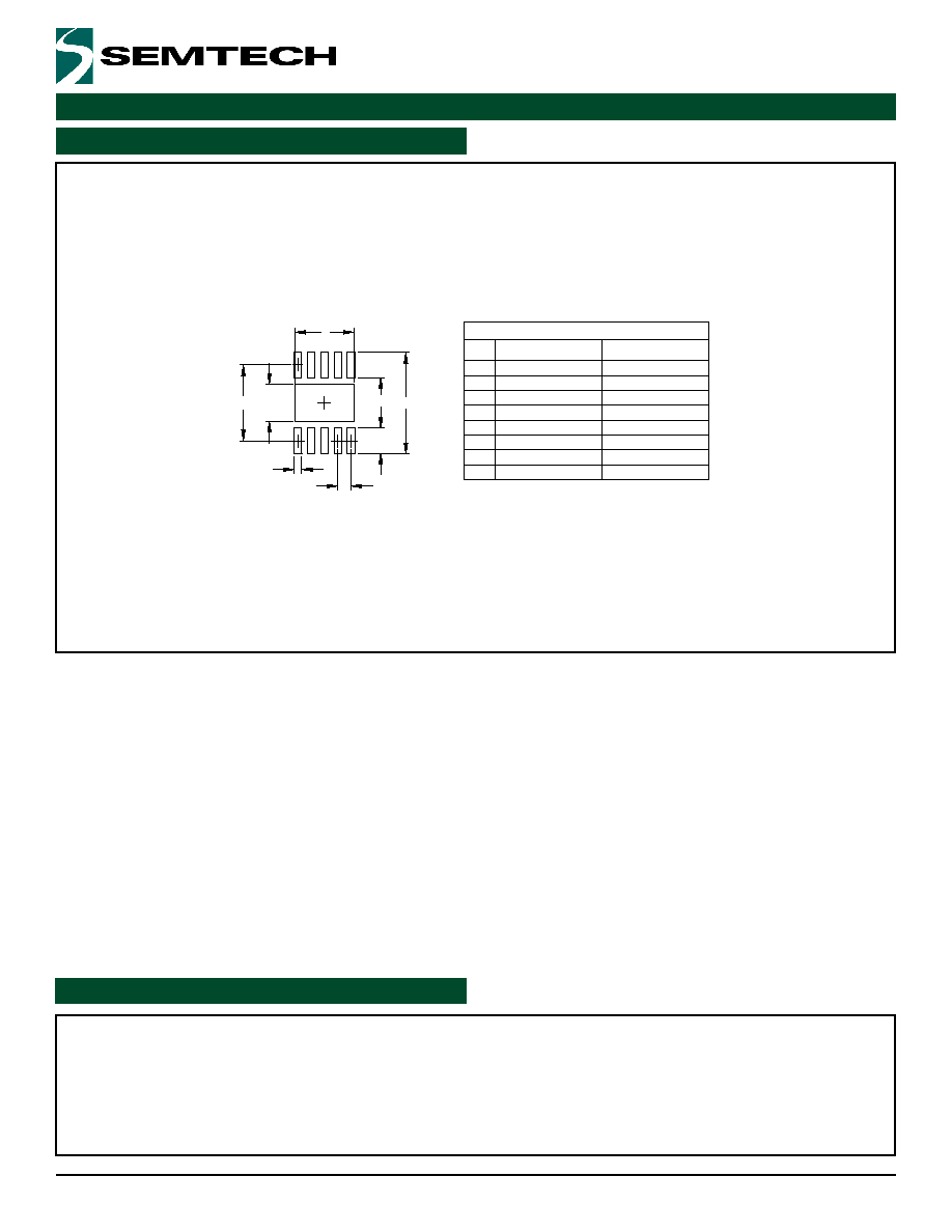
OutlineDrawing-MLPD-0
MIN
aaa
bbb
b
e
L
N
D
C
E
A1
A2
A
DIM
MILLIMETERS
NOM
DIMENSIONS
MAX
NOM
INCHES
MIN
MAX
.114 .118 .122 2.90 3.00 3.10
-
-
-
-
(LASER MARK)
INDICATOR
PIN 1
1
N
2
NOTES:
CONTROLLING DIMENSIONS ARE IN MILLIMETERS (ANGLES IN DEGREES).
COPLANARITY APPLIES TO THE EXPOSED PAD AS WELL AS TERMINALS.
2.
1.
.003
.007
.042
10
.009
.048
-
.000
.031
(.008)
0.08
0.23
10
.011
.052
0.18
1.06
.039
-
.002
-
0.00
0.80
1.31
0.30
1.21
-
0.05
1.00
(0.20)
.004
0.10
0.50 BSC
.020 BSC
0.30
.012
.020
.016
0.40 0.50
A
aaa C
A2
SEATING
PLANE
A1
A
bxN
bbb
C A B
B
e
C
C
D
LxN
E
E
.074 .079 .083 1.87 2.02 2.12
2
2005SemtechCorp.
www.semtech.com
POWER MANAGEMENT
SC635
SemtechCorporation
PowerManagementProductsDivision
200FlynnRoad,Camarillo,CA302
Phone:(805)498-2111FAX:(805)498-3804
ContactInformation
.087
.055
2.20
1.40
.150
.020
.012
.037
3.80
0.30
0.95
0.50
(.112)
.075
1.90
(2.85)
K
H
X
THIS LAND PATTERN IS FOR REFERENCE PURPOSES ONLY.
CONSULT YOUR MANUFACTURING GROUP TO ENSURE YOUR
COMPANY'S MANUFACTURING GUIDELINES ARE MET.
NOTES:
1.
INCHES
DIMENSIONS
G
K
H
X
Y
P
Z
C
DIM
MILLIMETERS
Y
Z
G
(C)
P
LandPattern-MLPD-0