doc5-703-700-ds-105_draft01.qxd
SerialCoderTM 700 UR5HC703-700
Extremely Low-Power Keyboard
Encoder Interfaces RS-232
SerialCoder, KeyCoder, and Self-Power
Management are trademarks of Semtech
Corporation. All other trademarks belong to their
respective companies.
Copyright ©1999-2001 Semtech Corporation
DOC5-703-700-DS-105
www.semtech.com
1
HID & SYSTEM MANAGEMENT PRODUCTS, KEYCODERTM FAMILY
DESCRIPTION
FEATURES
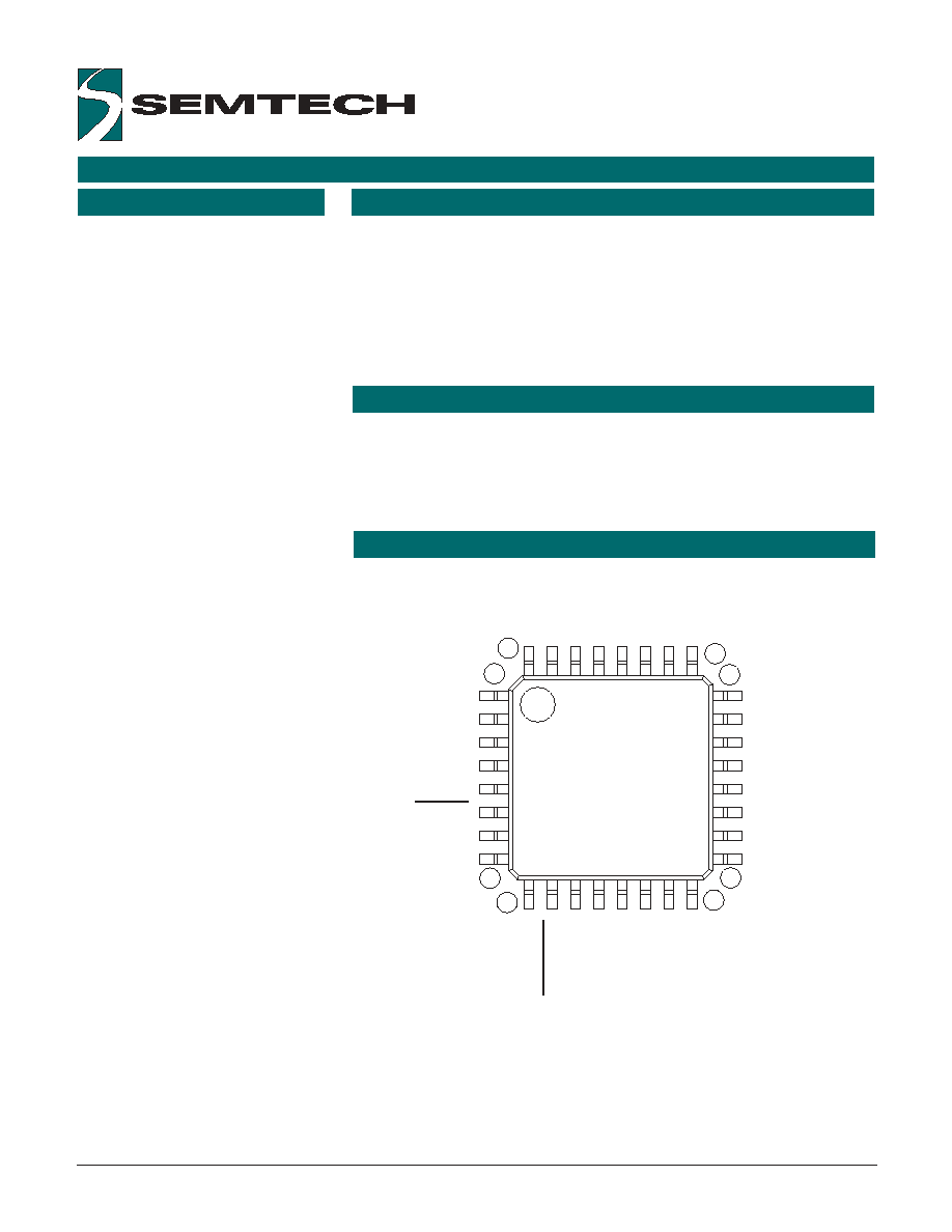
1
8
9
32
25
24
16
17
COL3
COL4
COL5
COL6
VDD2
RESET
VSS2
VDD
ROW6
ROW5
ROW4
ROW3
ROW2
ROW1
ROW0
RxD
OCSIN
OSCOUT
VSS
COL7
COL8
COL9
COL10
COL11
ROW7
COL12
TxD
COL13
HS
COL0
COL1
COL2
UR5HC703-700-FG
LQFP
· 8 x 14 keyboard matrix encoding
· IC is independent of the keyboard
layout
· Extremely low-power operation,
transparent to the host
· Typical current consumption of less
than 1 µA at room temperature; 10
µA at 85°C
· 9600 Baud 8N1 serial data format
· Direct connection to RS-232
signals from the host UART
· Simple, proprietary serial protocol
· Robust algorithm for ghost-key
elimination
· Self-Power ManagementTM, sleeps
between keystrokes
The SerialCoderTM 700
UR5HC703-700 is an extremely low-
power, "off-the-shelf" serial keyboard
encoder. Robust, tiny and flexible,
the IC is a good match for any
application where the use of
complicated keyboard protocols are
not required and where
asynchronous serial interface
hardware is available.
The SerialCoderTM 700 provides
Self-Power ManagementTM and
draws its power entirely from the
host device. It is ideal for use in
add-on keyboards for handheld and
cellular / web phones and other
portable applications.
Self-Power ManagementTM is
transparent to the host. Power
consumption is reduced to just the
circuit's leakage when all keys are
released. The average current
consumption is less than 1 µA at
room temperature and 10 µA at
85°C.
If a key or group of keys stays in the
depressed position for ten minutes
(with no other keyboard activity), the
IC shuts down to save power.
The SerialCoderTM 700 is simple to
implement. It requires few external
components and utilizes a tiny, low-
profile 32-pin LQFP package that
measures 7mm x 7mm.
APPLICATIONS
· Built-in keyboards for personal
digital assistant (PDA) and hand-
held PC (H/PC) devices
· Add-on accessory keyboards for
PDA and H/PC devices
· Portable personal computers
· Instrumentation
· Remote control
· Cellular phones
PIN ASSIGNMENTS
PRELIMINARY
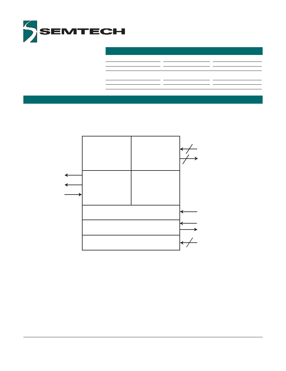
SERIALCODERTM 700 FUNCTIONAL DIAGRAM
ORDERING CODE
Copyright ©1999-2001 Semtech Corporation
DOC5-703-700-DS-105
www.semtech.com
2
4
Data
Buffer
Key
Matrix
Interface
Communication
Interface
Matrix
Scan Logic
Reset Logic
Oscillator
Power Supply
_RESET
OSCIN
_OSCOUT
8
14
R0-R7
C0-C13
UR5HC703-700
TxD
RxD
HS
Package Options
Pitch
Ta = -20° C to +85° C
32-pin, Plastic LQFP
0.8 mm
UR5HC703-700-FG
Other Materials
Type
Order number
SerialCoderTM 700 eval. kit
Evaluation kit
EVK5-703-700
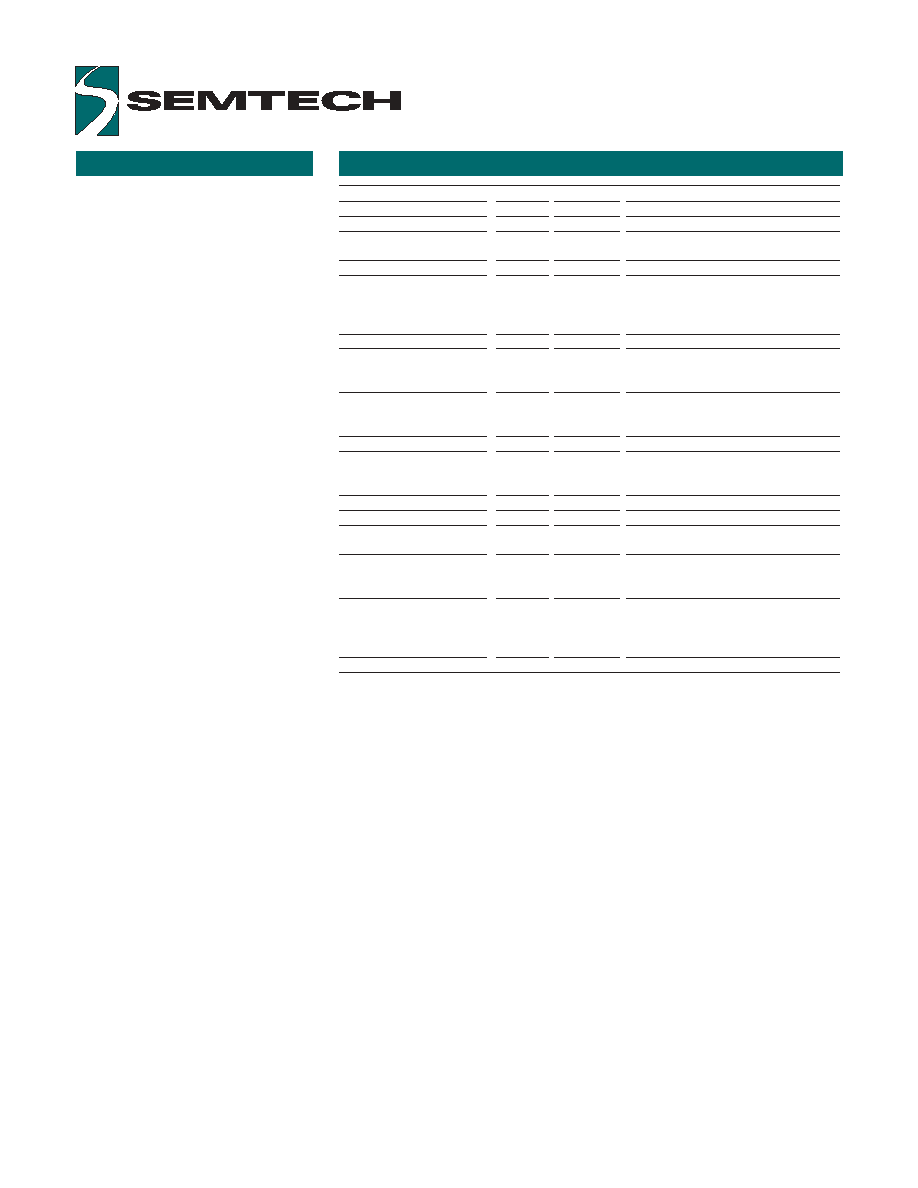
PIN DEFINITIONS
Copyright ©1999-2001 Semtech Corporation
DOC5-703-700-DS-105
www.semtech.com
3
Mnemonic
Pin #
Type
Name and Function
Power Supply
V
DD
, V
DD
2
8, 5
PWR
Positive supply voltage
V
SS
, V
SS
2
11, 7
PWR
Negative power supply:
Signal ground
Reset
_RESET
6
I
Hardware reset pin: Reset input
for orderly start-up; low logic level is
required whenever V
DD
is below
minimum operating voltage
Oscillator pins
OSCIN
9
I
Oscillator input: connect ceramic
resonator with built-in load capacitors;
2 MHz operating frequency
_OSCOUT
10
O
Oscillator output: connect
ceramic resonator with built-in load
capacitors
Host Interface
TxD
27
O
Serial data output: idle at 0V,
non-inverted data (direct connection to
RS232 port)
RxD
17
I
Serial data input
HS
29
O
"Hot" synchronization signal
Scanned
matrix pins
ROW0-ROW7
18-25
I
Row matrix inputs with pulsed
pull-up current sources
COL0-COL13
30-32,
O
Column matrix output, open drain
1-4,
12-16,
26, 28
Note: An underscore before a pin mnemonic denotes an active low signal.
PROTOCOL
The SerialCoderTM 700 uses a
proprietary serial protocol (patent
pending) for two-way
communication with the host
device. The specification for this
protocol is available, subject to a
non-disclosure agreement (NDA),
to customers and driver
developers. This protocol allows
the host device to save significant
power, by indicating to the host
device when it can lower its power
consumption to a minimum. This
flexible protocol can also
accommodate additional types of
data if desired; for example,
position data from a pointing stick
embedded in the keyboard.

"GHOST" KEYS
KEYBOARD SCANNER
Copyright ©1999-2001 Semtech Corporation
DOC5-703-700-DS-105
www.semtech.com
4
In any scanned contact switch
matrix, whenever three keys
defining a rectangle on the switch
matrix are pressed at the same
time, a fourth key positioned on the
fourth corner of the rectangle is
sensed as being pressed. This is
known as the "ghost" or "phantom"
key problem.
Figure 1: "Ghost" or "Phantom" Key
Problem
Although the problem cannot be
totally eliminated without using
external hardware, there are
methods to neutralize its negative
effects for most practical
applications. Keys that are
intended to be used in
combinations should be placed in
the same row or column of the
matrix, whenever possible. Shift
keys (Shift, Alt, Ctrl, Window)
should not reside in the same row
(or column) as any other keys. The
SerialCoderTM has built-in
mechanisms to detect the
presence of "ghost" keys.
Actual key presses
"Ghost"
Key
The encoder scans a keyboard organized as an 8 row by 14 column matrix
for a maximum of 112 keys. Smaller size matrixes can also be
accommodated by simply leaving unused pins open. The SerialCoderTM
provides internal pull-ups for the row input pins. When active, the encoder
selects one of the column lines (C0-C13) every 512 µS and then reads the
row data lines (R0-R7). A key closure is detected as a zero in the
corresponding position of the matrix.
A complete scan cycle for the entire keyboard takes approximately 9.2 ms.
Each key found pressed is debounced for a period of 20 ms. Once the
key is verified, the corresponding key code(s) are loaded into the transmit
buffer of the serial communication channel.
N-key rollover means the code(s) corresponding to each key press are
transmitted to the host system as soon as that key is debounced, indepen-
dent of the release of other keys.
When a key is released, the corresponding break code is transmitted to the
host system. Several keys can be held pressed at the same time.
However, if two or more key closures occur within a time interval of less
than 5 ms, an error flag is set, and those closures are not processed. This
feature protects against the effects of accidental key presses.
The SerialCoderTM 700 achieves uniquely low system power consumption,
due partly to Self-Power ManagementTM, and partly to the proprietary
protocol the IC uses to communicate with the the host system driver. Self-
Power ManagementTM powers down the IC between key presses; a key
press wakes up the IC immediately without losing any key data. The
protocol allows the host system to power down the power-wasting charge
pumps (for the communications interface) after a short period of inactivity.
Alerting the host on connection
When a keyboard assembly (including the SerialCoderTM 700 and the
recommended components) is plugged into a host system, the
SerialCoderTM 700 sends an identification code to the host, and forces the
host into a state where the host can acknowledge the code. After the host
receives and acknowledges this code, the host is aware that the keyboard
assembly is connected, and the host can then choose what to do next.
For example,
(1) The host can choose to enter a fully awakened state, and turn on the
screen, etc.
(2) If no keys have been pressed, the host can choose to return to a sleep
state.
N-KEY ROLLOVER
POWER MANAGEMENT

EVALUATION BOARD NOTE
Copyright ©1999-2001 Semtech Corporation
DOC5-703-700-DS-105
www.semtech.com
5
Note: Jumper Setting
When using the SerialCoderTM 700 evaluation board, and powering the IC
from the PDA interface, jumper 3 (J3) must be open; when powering from
the RS232 port, jumper 3 must be closed.