LapCoder
TM
UR5HCFJ8
Low-Power Keyboard
Encoder for Portable Systems
LapCoder is a trademark of Semtech Corp. All
other trademarks belong to their respective
companies.
Copyright Semtech, 1997-2001
DOC5-FJ8-DS-107
www.semtech.com
1
HID & SYSTEM MANAGEMENT PRODUCTS, KEYCODER
TM
FAMILY
DESCRIPTION
FEATURES
The LapCoder
TM
is a versatile, low-
power keyboard encoder for
portable systems. The UR5HCFJ8
provides two bi-directional channels
for communication with a BIOS-
compatible system as well as
any optional keyboard-compatible
devices, such as a 101/102 desktop
keyboard.
The UR5HCFJ8 fully supports the
IBM standard keyboard
communication protocol; each key
press generates one of the scan
codes designated in the IBM
Technical Reference Manuals.
The keyboard encoder handles
the scanning, debounce, and
encoding of 82 keys organized on
an 8x16 matrix and supports
embedded numeric keypad
functions as well as alternate scan
codes for specific keys, so that a
keyboard with only 82 keys is able
to emulate the functionality of a
101/102 keyboard.
In addition to the system's keyboard
communication port the UR5HCFJ8
provides a fully functional keyboard
input port that can be used by a
standard 82/101/102 keyboard or
another 8042-compatible device,
such as an external numeric
keypad, an OCR, or a bar-code
reader. Input from both the matrix
and the external device is
multiplexed and presented to the
system as if it were coming from a
single source.
The features of UR5HCFJ8 make it
ideal for use in PC/AT/PS/2
laptop/notebook designs that utilize
the Fujitsu FKB7211 low-profile, full-
travel membrane keyboard.
� Laptop/Notebook
� Portable Equipment
� Industrial Keyboards
� POS Terminals
� Public Information Kiosks
� Low-power, single IC suitable for
3V battery-operated systems
� Implements all functions of an
101/102 keyboard with only
82-keys
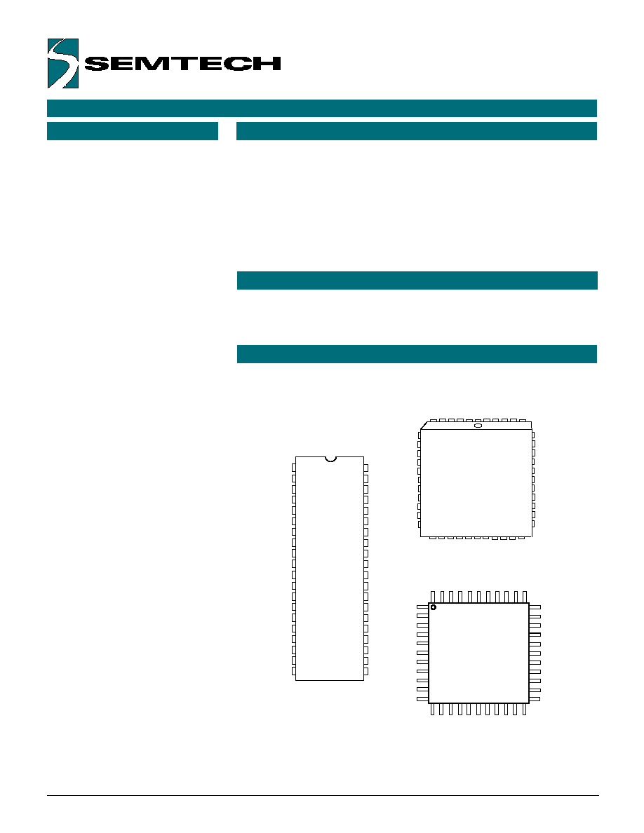
� Available in DIP, PLCC and Quad
Flat packages
� Custom versions available in small
or large quantities
� Interfaces the Fujitsu FKB7211 or
other similar laptop/notebook
keyboards to a BIOS-compatible
systems
� AT / PS/2-compatible
� Interfaces an external keyboard /
keypad or other 8042-compatible
devices
1
2
3
4
5
6
7
8
9
10
11
12
13
14
15
16
17
18
19
20
40
39
38
37
36
35
34
33
32
31
30
29
28
27
26
25
24
23
22
21
_RESET
_IRQ
VX
NL
R6
RP
KD
KC
EKC
EKD
CL
C0
C1
C2
C3
C4
C5
C6
C7
VSS
VCC
OSCI
OSCO
EKC1
R7
SL
R5
R4
R3
R2
R1
R0
C8
C9
C10
C11
C12
C13
C14
C15
DIP
R6
RP
KD
KC
EKC
EKD
CL
C0
C1
C2
C3
NL
VX
_IRQ
_RESET
NC
NC
VCC
OSCI
OSCO
EKC1
R7
SL
R5
R4
R3
R2
R1
R0
C8
C9
C10
C11
C4
C5
C6
C7
NC
GND
C15
C14
C13
C12
NC
QFP
R6
NL
VX
VXA
_IRQ
_RESET
VCC
OSCI
OSC0
EKC1
NC
RP
KD
KC
EKC
EKD
CL
C0
C1
C2
C3
C4
R7
SL
R5
R4
R3
R2
R1
R0
C8
C9
C10
NC
C5
C6
C7
GND
NC
C15/KT
C14
C13
C12
C11
40
1
6
7
12
17
18
23
28
29
34
39
PLCC
APPLICATIONS
PIN DESCRIPTIONS
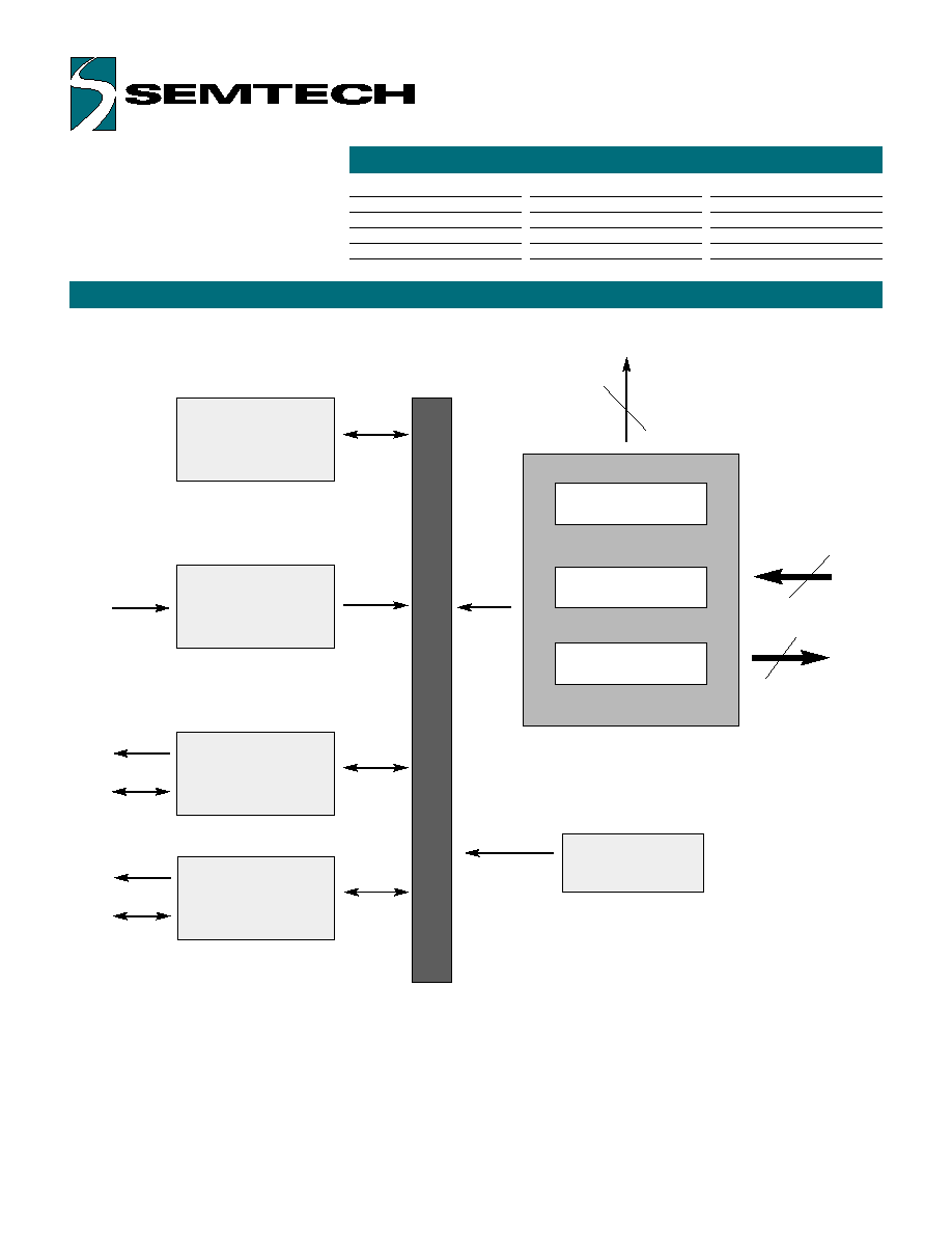
FUNCTIONAL DIAGRAM
ORDERING CODE
Copyright Semtech, 1997-2001
DOC5-FJ8-DS-107
www.semtech.com
2
Data Buffer
Interrupt Control
PC
Communication
Channel
EKC1
KC
KD
Keyboard Encoder
Mode Control
Status LEDs
Row Data Inputs
Column Select
Ouputs
NL/CL/SL
3
8
16
C0-
C15
R0-
R7
Package options
40-pin Plastic DIP
44-pin, Plastic PLCC
44-pin, Plastic QFP
Pitch In mm's
2 54 mm
1.27 mm
0.8 mm
TA = -40�C to +85�C
UR5HCFJ8-P
UR5HCFJ8-FN
UR5HCFJ8-FB
8042 Emulation
(External Keyboard)
Communication
Channel
EKC
EKD

FUNCTIONAL DESCRIPTION
PIN DEFINITIONS
Copyright Semtech, 1997-2001
DOC5-FJ8-DS-107
www.semtech.com
3
The UR5HCFJ8 consists functionally
of six major sections (see Functional
Diagram, previous page). These
are the Keyboard Encoder, the
Mode Control Unit, the PC
Communication Channel, the Data
Buffer, the Interrupt Control and the
8042 Emulation Channel. All
sections communicate with each
other and operate concurrently.
Mnemonic DIP
PLCC
QFP
Type
Name and Function
VCC
40
44
38
I
Power Supply: +5V
VSS
20
22
17
I
Ground
OSCI
39
43
37
I
Oscillator input
OSCO
38
42
36
O
Oscillator output
_RESET
1
1
41
I
Reset: Apply 0V to provide orderly start-up
EKC1
37
41
35
External Keyboard Clock 1: Connects
to external keyboard Clock Line and is used
to generate an interupt for every Clock Line
transition.
VX
3
4
43
I
Tie to Vcc
VXA
3
I
Tie to Vcc
RP
6
7
2
I
Reserved: Ties to Vcc
KC
8
9
4
I/O
Keyboard Clock: Connects to PC
keyboard port clock line
KD
7
8
3
I/O
Keyboard Data: Connects to
PC port data line
EKD
10
11
6
I/O
External Keyboard Data: Connects to
external keyboard Data Lne
ECK
9
10
5
I/O
External Keyboard Clock: Connects
to external keyboard Clock Line
_IQR
2
2
42
I
Interrupt Line: Reserved for low-power
applications
R0-R5
29-34
32-37
27-32
I
Row Data Inputs
R6
5
6
1
I
R7
36
39
34
I
C0-C7
12-19
13-17
8-15
O
Column Select Outputs: Selects 1 of
19-21
O 16 columns
C8-C15
28-21
31-24
26-23
O
21-18
O
CL
11
12
7
O
Caps Lock LED
NL
4
5
44
O
Num Lock LED
SL
35
38
33
O
Scroll Lock LED
NC
18
16,22
No Connects: These pins are unused.
23,40
39,40
Note: An underscore before a pin mnemonic denotes an active low signal.
KEYBOARD ENCODER
The controller continuously scans a
keyboard organized as an 8 row by
16 column matrix for a maximum of
128 keys. Smaller-size keyboards
are supported provided that all
unused row lines are pulled to Vcc.
The IC selects 1 of the 16 column
lines (C0-C15) every 512 mS and
then reads the row data lines (R0-
R7). A key closure is detected as a
0 in the corresponding position of
the matrix. A complete scan cycle
for the entire keyboard takes
approximately 9.2 mS. Each key
found pressed is debounced for a
period of 20 mS. Once the key is
verified, the corresponding key
code(s) are loaded into the transmit
buffer of the PC Communication
Channel.
Switch Matrix Encoding
Each matrix location is programmed
to represent either a single key or a
key combination of the IBM 101/102
standard keyboard.
Scan Code Table Sets
The UR5HCFJ8 supports all three
scan code table sets. Scan Code
Sets 1 and 2 are the default sets for
AT/PS/2 systems. Scan Code Table
Set 3 allows the user to program
individual key attributes such as
Make/Break and Typematic or
Single-Touch Action. For more
information, refer to the IBM
Technical Reference Manuals.
KEYBOARD ENCODER, (CON'T)
MODE CONTROL
Copyright Semtech, 1997-2001
DOC5-FJ8-DS-107
www.semtech.com
4
Embedded Numeric Keypad
The UR5HCFJ8 implements an
embedded numeric keypad. The
Numeric Keypad Function is
invoked by pressing the Num Lock
Key.
FN Key
A special FN Key has been
implemented to perform the
following functions while it is held
pressed:
� Function Key F1 becomes F11
� Function Key F2 becomes F12
� Ctrl Left Key becomes Ctrl Right
� Alt Left Key becomes Alt Right
If Num Lock is set:
� Embedded numeric keypad keys
become regular keys.
If Num Lock is not set:
� Embedded numeric keypad keys
provide the same codes as a
numeric keypad when the Num
Lock is not set (Arrow Keys, PgUp,
PgDn, etc.)
Status LED indicators
The controller provides interfacing
for three LED shift status indicators.
All three pins are active low to
indicate the status of the host
system (Num Lock, Caps Lock and
Scroll Lock). They are set by the
system (AT/PS/2 protocol).
Operating modes are defined by the logic level of the mode pin in the Mode
Control Unit.
N-Key Rollover
In this mode, the code(s) corresponding to each key press are transmitted
to the host system as soon as that key is debounced, independently of the
release of other keys. If a key is defined to be Typematic, the
corresponding code(s) will be transmitted while that key is held pressed.
When the key is released, the corresponding break code(s) are then
transmitted to the host system. If the released key happens to be the most
recently pressed, then Typematic Action is terminated. There is no limitation
to the number of keys that can be held pressed at the same time. However,
two or more key closures, occurring within a time interval of less than 5 mS,
will set an error flag and will not be processed. This procedure protects
against the effects of accidental key presses.
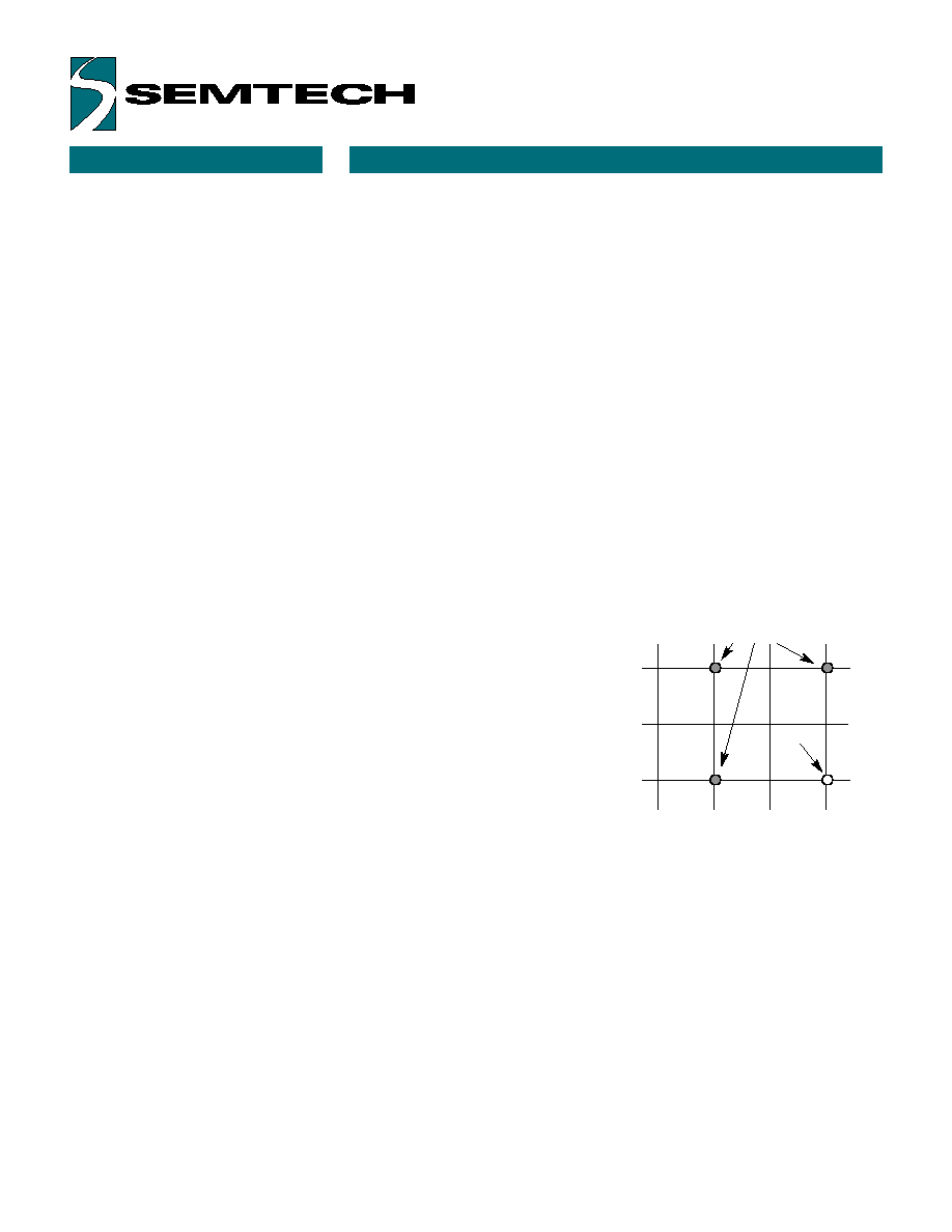
"Ghost" Keys
In any scanned contact switch matrix, whenever three keys defining a
rectangle on the switch matrix are held pressed at the same time, a fourth
key positioned on the fourth corner of the rectangle is sensed as being
pressed. This is known as the "ghost" or "phantom" key problem. Although
the problem cannot be totally
eliminated without using external
hardware, there are methods to
neutralize its negative effects for most
practical applications. Keys that are
intended to be used in combinations or
are likely to be pressed at the same
time by a fast typist (i.e., keys located
in adjacent positions on the keyboard)
should be placed in the same row or
column of the matrix, whenever
possible. Shift keys (Shift, Alt, Ctrl)
should not reside in the same row (or
column) with any other keys.
The UR5HCFJ8 has built-in mechanisms to detect the presence of "ghost"
keys, thus eliminating the necessity of external hardware.
Actual key presses
"Ghost"
Key
Figure 1: "Ghost" or "Phantom" Key
Problem

SPECIAL HANDLING
PC COMMUNICATION
Copyright Semtech, 1997-2001
DOC5-FJ8-DS-107
www.semtech.com
5
The UR5HCFJ8 implements all the
standard functions of
communication with a BIOS-
compatible PC/XT or AT/PS/2 host
system. Two lines, KC and KD,
provide bi-directional clock and
data signals. In addition, the
UR5HCFJ8 supports all commands
from and to the system, as
described in the IBM Technical
Reference Manuals.
The following table shows the
commands that the system may
send and their values in hex.
Command
Hex Value
Set/Reset Status
ED
Indicators
Echo
EE
Invalid Command
EF
Select Alternate
F0
Scan Codes
Invalid Command
F1
Read ID
F2
Set Typematic
F3
Rate/Delay
Enable
F4
Default Disable
F5
Set Default
F6
Set All Keys
Typematic
F7
Make/Break
F8
Make
F9
Typematic/Make/Break
FA
Set Key Type
Typematic
FB
Make/Break
FC
Make
FD
Resend
FE
Reset
FF
Table 2: Keyboard Commands from the
System (AT/PS/2 protocol)
These commands are supported in
the AT/PS/2 protocol and can be
sent to the keyboard at any
time.The following table shows the
commands that the keyboard may
send to the system.
Command
Hex Value
Key Detection
00*
Error/Overrun
Keyboard ID
83AB
BAT Completion Code
AA
BAT Failure Code
FC
Echo
EE
Acknowledge (Ack)
FA
Resend
FE
Key Detection
Error/Overrun
FF**
*Code Sets 2 and 3
**Code Set 1
Table 3: Keyboard Commands to the
System (AT/PS/2 protocol)
8042 Emulation Channel
The UR5HCFJ8 fully emulates a
system's keyboard port, available to
a standard 82/101/102 external
keyboard or other 8042-compatible
device. Communication with a
keyboard-compatible device is
accomplished by clock and data
lines via EKC and EKD pins,
respectively. A third pin, EKC1,
connects to the Clock Line and
interrupts the controller whenever
the external device initiates a
communication session. When
power is first applied, the controller
proceeds with the standard reset
sequence with the external device.
Data and commands initiated from
the external device are buffered in
the controller's FIFO along with data
from the scanned matrix, and then
are presented to the system as if
they were coming from a single
source. After they are
acknowledged, commands and
data from the system are
transmitted to the external device.
Hot Plug-Ins of External
Device
The UR5HCFJ8 will detect the
presence of an external device.
If an external keyboard or other
device was not connected during
power-on and is connected at a
later time, the encoder will proceed
with the normal reset routine in
order to properly initialize the
external keyboard. After
communication has been
established, the encoder will
continue to check for the presence
of the external keyboard. While the
external device is connected, the
encoder will not enter the sleep
mode. If the device is
disconnected at a later time, the
encoder will become aware of it.
If a subsequent connection takes
place, the controller will reinitiate a
reset sequence. This unique
feature allows the user to connect
or disconnect an external device at
any time without having to reset the
system.
Shift Status LEDs
Shift Status LEDs (Num Lock, Caps
Lock and Scroll Lock) indicate the
status of the system and are
controlled by commands sent from
the system. Set/Reset Status
Indicator commands from the
system will be executed both by the
external keyboard and the scanned
matrix. For example, if the user
presses the Caps Lock Key on
either keyboard, the Caps Lock
LED will be affected in both
keyboards. The LED status
indicators are properly set after
every new connection of an external
keyboard.