GreenCoder
TM
UR5HCFJL
Zero-Power
TM
Keyboard
Encoder for Portable Systems
GreenCoder is a trademark of Semtech Corp. All
other trademarks belong to their respective
companies.
Copyright Semtech, 1997-2001
DOC5-FJL-DS-106
www.semtech.com
1
HID & SYSTEM MANAGEMENT PRODUCTS, KEYCODER
TM
FAMILY
DESCRIPTION
FEATURES
The GreenCoder
TM
(UR5HCFJL) is
a unique, Zero-Power
TM
keyboard
encoder that provides an optimum
performance level for both battery-
operated and desktop systems.
The GreenCoder
TM
scans,
debounces and encodes an 8 X 16
keyboard matrix, and will provide
direct drive for 3 LEDs and two
bi-directional channels for
communication with a BIOS-
compatible system as well as an
additional keyboard-compatible
device. It fully supports all three
PS/2 scan code sets and will
implement up to three alternate
keyboard layers for full 101/102
functionality.
The GreenCoder
TM
employs a
unique Self-Power Management
TM
method that reduces the power
consumption of the keyboard
sub-system to an unprecedented
minimum, transparently and without
user intervention. In "Active" mode,
the encoder consumes less than 2
mA (Typ @5V). In "Sleep" mode the
encoder consumes less than 2 �A
(Typ @5V) The encoder can even
nap between keystrokes and
therefore it is rarely active and
rarely consumes significant levels of
power.
A "stand-by" mode (600 �A Typ
@5V) is entered for as long as
a periodic task is active. After a
programmed period of user
inactivity the GreenCoder
TM
gradually dims the LEDs for
further power savings.
The GreenCoder
TM
is ideal for use in
battery laptop/notebook designs
and Energy Star compliant
keyboards.
R6
NL
VX
NC
DRV
_RESET
VCC
OSCI
OSCO
EKC1
NC
OPT
KD
KC
EKC
EKD
CL
C0
C1
C2
C3
C4
R7
SL
R5
R4
R3
R2
R1
R0
C8
C9
C10
NC
C5
C6
C7
GND
NC
C15
C14
C13
C12
C11
40
1
6
7
12
17
18
23
28
29
34
39
PLCC
1
2
3
4
5
6
7
8
9
10
11
12
13
14
15
16
17
18
19
20
40
39
38
37
36
35
34
33
32
31
30
29
28
27
26
25
24
23
22
21
_RESET
DRV
VX
NL
R6
OPT
KD
KC
EKC
EKD
CL
C0
C1
C2
C3
C4
C5
C6
C7
GND
VCC
OSCI
OSCO
EKC1
R7
SL
R5
R4
R3
R2
R1
R0
C8
C9
C10
C11
C12
C13
C14
C15
DIP
R6
OPT
KD
KC
EKC
EKD
CL
C0
C1
C2
C3
NL
VX
DRV
_RESET
NC
NC
VCC
OSCI
OSCO
EKC1
R7
SL
R5
R4
R3
R2
R1
R0
C8
C9
C10
C11
C4
C5
C6
C7
NC
GND
C15
C14
C13
C12
NC
QFP
� Laptop/Notebook
� Portable Equipment
� Energy Star Compliant
� Medical Instruments
� Palmtops/ PDAs
� Wakes-up only to respond to an
external event and for a minimum
period of time (2 mA current
consumption)
� Provides interface for external
keyboard/keypad or other 8042-
compatible device
� Custom versions available in small
or large quantities
� Optimized power-saving operation
with idle consumption of less
than 2 �A
� Programmable LED dimming for
further power savings
� Ready to interface to Fujitsu's
7316, 7654,7656, and
1406 keyboards
� 3, 3.3 and 5 Volt operation
APPLICATIONS
PIN ASSIGNMENTS
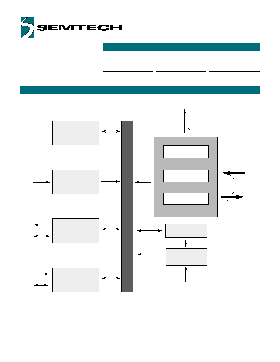
FUNCTIONAL DIAGRAM
ORDERING CODE
Copyright Semtech, 1997-2001
DOC5-FJL-DS-106
www.semtech.com
2
XX = 16 for FKB7136,06 for FKB1406 matrix compatibility
Data Buffer
Interrupt Control
PC
Communication
Channel
8042 Emulation
(External Keyboard)
Communication
Channel
EKC1
KC
KD
EKC
EKD
Keyboard Encoder
Mode Control
Status LEDs
Row Data Inputs
Column Select
Ouputs
NL/CL/SL
3
8
16
DRV
16-Bit Timer
C0-C15
R0-R7
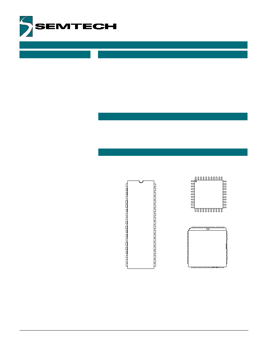
Package options
40-pin Plastic DIP
44-pin, Plastic PLCC
44-pin, Plastic QFP
Pitch In mm's
2 54 mm
1.27 mm
0.8 mm
TA = -40�C to +85�C
UR5HCFJL-XX-P
UR5HCFJL-XX-FN
UR5HCFJL-XX-FB

FUNCTIONAL DESCRIPTION
PIN DEFINITIONS
Copyright Semtech, 1997-2001
DOC5-FJL-DS-106
www.semtech.com
3
The GreenCoder
TM
consists
functionally of seven major sections
(see Functional Diagram, previous
page). These are the Keyboard
Encoder, a 16-Bit Timer, the Mode
Control Unit, the Data Buffer, the
Interrupt Control, the PC Commun-
ication Channel and the 8042
Emulation Channel. All sections
communicate with each other and
operate concurrently.
Mnemonic DIP
PLCC
QFP
Type
Name and Function
VCC
40
44
38
I
Power Supply: +5V
VSS
20
22
17
I
Ground
OSCI
39
43
37
I
Oscillator input
OSCO
38
42
36
O
Oscillator output
_RESET
1
1
41
I
Reset: apply 0V to provide orderly start-up
EKC1
37
41
35
I
External Keyboard Clock 1:connects
to external keyboard clock line and is used
to generate an interrupt for every clock line
transmission
VX
3
4
43
I
Tie to Vcc
OPT
6
7
2
I
Used for options selection
KC
8
9
4
I/O
Keyboard Clock: connects to PC
keyboard port data line
KD
7
8
3
I/O
Keyboard Data: connects to
PC port data line
EKD
10
11
6
I/O
External Keyboard Data: connect to
external keyboard clock line
EXC
9
10
5
I/O
External Keyboard Clock 1: connects
to external keyboard data line
DRV
2
2
42
I
Wake-up line: used for sleep mode
R0-R5
29-34
32-37
27-32
I
Row Data Inputs
R6
5
6
1
I
R7
36
39
34
I
C0-C4
12-16
13-17
8-12
I/O
Column Select Outputs: select 1 of 16
C5-C7
17-19
19-21
13-15
O
columns
C8-C15
28-21
31-24
26-18
O
CL
11
12
7
O
Caps Lock LED
NL
4
5
44
O
Num Lock LED
SL
35
38
33
O
Scroll Lock LED
NC
3,18
39-40
No Connects: these pins are unused
23,40
16,22
Note: An underscore before a pin mnemonic denotes an active low signal.
KEYBOARD ENCODER
The encoder scans a keyboard
organized as an 8 row by 16 column
matrix for a maximum of 128 keys.
Smaller-size keyboards are support-
ed provided that all unused row
lines are pulled to Vcc. When
active, the encoder selects 1 of the
16 column lines (C0-C15) every 512
�S and then reads the row data
lines (R0-R7). A key closure is
detected as a 0 in the
corresponding position of the matrix.
A complete scan cycle for the entire
keyboard takes approximately 9.2
mS. Each key found pressed is
debounced for a period of 20 mS.
Once the key is verified, the
corresponding key code(s) are
loaded into the transmit buffer of the
PC keyboard communication
channel.
Scan Code Table Sets
The UR5HCFJL supports all three
scan code table sets. Scan Code
Table Set 3 allows the user to
program individual key attributes
such as Make/Break and Typematic
or Single-Touch Action. For more
information, refer to the IBM Tech-
nical Reference Manuals. Custom
scan code tables, including macros,
are also available.

KEYBOARD ENCODER, (CON'T)
MODE CONTROL
Copyright Semtech, 1997-2001
DOC5-FJL-DS-106
www.semtech.com
4
Embedded Numeric Keypad
The GreenCoder
TM
implements an
embedded numeric keypad. The
Numeric Keypad Function is
invoked by pressing the Num Lock
Key.
FN Key
A special FN Key has been
implemented to perform the
following functions while it is held
pressed:
� Function Key F1 becomes F11
� Function Key F2 becomes F12
� Control Left Key becomes Ctrl
Right
� Embedded numeric keypad keys
become regular keys
If Num Lock is not set:
� Embedded numeric keypad keys
provide the same codes as a
numeric keypad when the Num
Lock is not set (Arrow keys, PgUp,
PgDn, etc.)
Status LED indicators
The controller provides an interface
for three LED shift status indicators.
All three pins are active low to
indicate the status of the host
system (Num Lock, Caps Lock and
Scroll Lock) and are set by the
system. After approximately a one-
minute period of keyboard inactivity,
LEDs are dimmed to conserve
power. They are set to full
brightness again upon a new
keystroke.
N-Key Rollover
In this mode, the code(s) corresponding to each key press are transmitted
to the host system as soon as that key is debounced, independently of the
release of other keys.
If a key is defined to be Typematic, the corresponding make code(s) will be
transmitted while the key is held pressed. When a key is released, the
corresponding break code(s) are then transmitted to the host system. If the
released key happens to be the most recently pressed, then Typematic
action is terminated. There is no limitation in the number of keys that can
be held pressed at the same time. However, two or more key closures,
occurring within a time interval less than 5 mS, will set an error flag and will
not be processed. This procedure protects against effects of accidental key
presses.
"Ghost" Keys
In any scanned contact switch matrix, whenever three keys defining a
rectangle on the switch matrix are held pressed at the same time, a fourth
key positioned on the fourth corner of the rectangle is sensed as being
pressed. This is known as the "ghost" or "phantom" key problem. Although
the problem cannot be totally eliminated without using external hardware,
there are methods to neutralize its negative effects for most practical
applications. Keys that are intended to
be used in combinations or are likely to
be pressed at the same time by a fast
typist (i.e., keys located in adjacent
positions on the keyboard) should be
placed in the same row or column of the
matrix whenever possible. Shift Keys
(Shift, Alt, Ctrl) should not reside in the
same row (or column) with any other
keys. The GreenCoder
TM
has built-in
mechanisms to detect the presence of a
"ghost" key, thus eliminating the
necessity of external hardware.
Actual key presses
"Ghost"
Key
Figure 1: "Ghost" or "Phantom" Key
Problem

8042 EMULATION CHANNEL
SPECIAL HANDLING
Copyright Semtech, 1997-2001
DOC5-FJL-DS-106
www.semtech.com
5
The GreenCoder
TM
fully emulates a
system's keyboard port, available to
a standard 84/85/101/102 external
keyboard or other 8042-compatible
device. Communication with a
keyboard-compatible device is
accomplished by clock and data
lines via EKC and EKD pins,
respectively. A third pin, EKC1 that
connects to the Clock Line,
interrupts the controller whenever
the external device initiates a
communication session.
When power is first applied, the
controller proceeds with the
standard reset sequence with the
external device. Data and
commands initiated from the
external device are buffered in the
controller's FIFO along with data
from the scanned matrix, and then
are presented to the system as if
they were coming from a single
source. Once they are
acknowledged, commands and
data from the system are then
transmitted to the external device.
Connection of External Device
The UR5HCFJL will detect the presence of an external device. If an
external keyboard or other device was not connected during power-on and
is connected at a later time, the encoder will proceed with the normal reset
routine in order to properly initialize the external device. After
communication has been established, the encoder will continue to check for
the presence of the external device. While the external device is
connected, the encoder will not enter the sleep mode. If the device is
disconnected at a later time, the encoder will become aware of it. If a
subsequent connection takes place, the controller will re-initiate a reset
sequence. This unique feature allows the user to connect or disconnect an
external device at any time without having to reset the system.
Shift Status LEDs
Shift Status LEDs (Num Lock, Caps Lock and Scroll Lock) indicate the
status of the system and are controlled by commands sent from the system.
Set/Reset Status Indicator Commands from the system will be executed
both by the external keyboard and the scanned matrix.
For example, if the user presses the Caps Lock Key on either keyboard, the
Caps Lock LED will be affected on both keyboards. The LED status
indicators are properly set after each new connection of an external
keyboard.