 | –≠–ª–µ–∫—Ç—Ä–æ–Ω–Ω—ã–π –∫–æ–º–ø–æ–Ω–µ–Ω—Ç: UR7HCTS2 | –°–∫–∞—á–∞—Ç—å:  PDF PDF  ZIP ZIP |

Semtech, the Semtech logo, ScreenCoder, and
Self-Power Management are marks of Semtech
Corporation. All other marks belong to their
respective companies.
Copyright ©2000-2004 Semtech Corporation
UR7HCTS2 data sheet v1.14 (2004-10-28)
www.semtech.com
1
UR7HCTS2 ScreenCoderÆ
PS/2, Asynchronous Serial, and SPI Interface
Touch Screen Controller
HID & SYSTEM MANAGEMENT PRODUCTS, SCREENCODERÆ FAMILY
DESCRIPTION
FEATURES
1
8
9
32
25
24
16
17
SYB/SW_AD
SXR/SE_AD
X
PWRS/SENSE_DR
V
SENSE_AD
VREF
_RESET
VSS2
VDD
_LB/_T
OUCH
XR2/SE2
YB2/SW2
YT2/NE2
XL2/NW2
HDA
T/_CTS/_A
TN
XDA
T
XCLK
_RB
SERSEL
TxD
SCLK
SOUT
_PWR_DOWN
SXL/NW_AD
SYT/NE_AD
HCLK/_RTS/_SS
XL1/NW1
YT1/NE1
YB1/SW1
XR1/SE1
VSS
_OSCOUT
OSCIN
UR7HCTS2-FG
LQFP
The UR7HCTS2 ScreenCoderÆ is
a touch screen controller with an
integrated digitizer. It works with
any 4-wire, 5-wire, or 8-wire
resistive touch screen, regardless
of size or manufacturer. The
controller interfaces to the host
system via PS/2, asynchronous
serial, or SPI (serial peripheral
interface).
Unlike standalone digitizer designs,
which relegate the entire workload
to the host processor, the low-
power-consuming UR7HCTS2
integrates the digitizer, controller,
and both host system and sensor
interfaces. This greatly reduces
design complexity, development,
integration effort, and cost.
The UR7HCTS2 performs all touch
detection (from finger or pen input),
noise and RF filtering, and error
elimination tasks, supplying fully
processed, stable position data to
the host processor.
The UR7HCTS2's internal power
management technique employs
proprietary motion algorithms and
advanced sampling technology,
allowing the UR7HCTS2 to
consume a mere 1 µA of current
while no event occurs.
The device also provides system
wake-up either by touching the
screen or moving a mouse
connected to its external PS/2 port.
The UR7HCTS2's power
consumption is 3 mA only while an
event occurs.
Semtech's proprietary algorithm
samples at a rate of 100 points per
second.
∑ Resolution of 1024 points per axis
and a sampling rate of 100 points
per second
∑ Accurate, quick touch response
triggers system wake-up
∑ Highly resistant to RF and other
noise sources
∑ External PS/2 port for the hot-plug
connection of a PS/2 mouse
∑ Interfaces host system via PS/2,
asynchronous serial, or SPI (serial
peripheral interface)
∑ Works with any 4-, 5-, or 8-wire
resistive touch screen, regardless
of size or manufacturer
∑ Low-power operation, typically less
than 1 µA
∑ Touch screen controller in an LQFP
package
∑ Notebook computers
∑ Next-generation cell phones
∑ Handheld PCs (H/PCs)
∑ PDAs
∑ Smart phones
∑ Interactive kiosks
∑ Point-of-sale (POS) terminals
APPLICATIONS
PIN ASSIGNMENTS
Copyright ©2000-2004 Semtech Corporation
UR7HCTS2 data sheet v1.14 (2004-10-28)
2
www.semtech.com
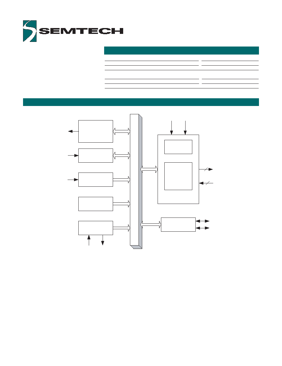
BLOCK DIAGRAM
ORDERING CODE
Package Options
Pitch
TA= -20∞ C to +85∞ C
32-pin plastic LQFP
0.8 mm
UR7HCTS2-FG
Other Materials
Type
Order number
UR7HCTS2 evaluation kit
Evaluation kit
EVK7-TS2
Host Interface
Communication Port
PS/2, SPI,
Asynchronous Serial
Power Management
Section
Power-On Reset
16 bit Timer
Oscillator Circuit
Sensor Interface
Switch Interf ace
Touch Panel
Interf ace
External PS/2 Port
Host
OSCIN
_OSCOUT
Left Button Right Button
Driv ers for Touch
Screen
Sense Line(s)
4
1-4
XCLK
XDAT
_RESET
_PWR_DOWN

FUNCTIONAL DESCRIPTION
PIN DEFINITIONS
Copyright ©2000-2004 Semtech Corporation
UR7HCTS2 data sheet v1.14 (2004-10-28)
www.semtech.com
3
Mnemonic
Pin/Lead Type
Name and Function
_PWR_DOWN
30
I
4/8-wire: hardware power down: tie high if
unused; 5-wire: leave open
VDD
8
P
Power supply
VSS
11
P
Ground
VSS2
7
P
Ground
_RESET
6
I
Reset: apply 0 V to provide orderly start-up
_OSCOUT
10
O
Oscillator output: open for external clock input or
one side of the ceramic resonator with built-in
load capacitors
OSCIN
9
I
Oscillator input: external clock input or one side
of the ceramic resonator with built-in load
capacitors
HCLK/_RTS/_SS
16
I/O (pu) PS/2: clock line to host; Serial: input, active low,
ready-to-send; SPI: input, active low, slave select;
HDAT/_CTS/_ATN
19
I/O (pu) PS/2: data line to host; Serial: output, clear-to-
send; SPI: ouput, attention
SCLK
28
I/O
PS/2: leave open; Serial: tie to ground;
SPI: clock line
SERSEL
26
I/O
PS/2: leave open;
Serial, SPI: tie to XR and XR2
SOUT
29
O
PS/2, Serial: leave unconnected; SPI: output data
TxD
27
O
PS/2, SPI: leave unconnected; Serial: output data
XCLK
17
I/O (pu) PS/2 clock signal from external mouse; leave
open if unused
XDAT
18
I/O (pu) PS/2 data signal from external mouse; leave
open if unused
_LB/_TOUCH
24
I/O (nd) 4/8-wire: left button, active low, strobed sampling;
5-wire: touch detection, active low
_RB
25
I/O (nd) Right button: active low, strobed sampling
SENSE_AD
4
I/O
4/8-wire: leave unconnected;
5-wire: connect to sense line
SXL/NW_AD
31
AI
Sense line: 4/8-wire: X Left; 5-wire: North West
SXR/SE_AD
2
AI
Sense line: 4/8-wire: X Right; 5-wire: South East
SYB/SW_AD
1
AI
Sense line: 4/8-wire: Y Bottom;
5-wire: South West
SYT/NE_AD
32
AI
Sense line: 4/8-wire: Y Top; 5-wire: North East
VREF
5
AI
Reference voltage for built-in A/D
XL1/NW1
15
I/O
Excitation driver: 4/8-wire: X Left;
5-wire: North West
XL2/NW2
20
I/O
Excitation driver: 4/8-wire: X Left;
5-wire: North West
XPWRS/SENSE_DRV 3
AI
4/8-wire: external mouse power sense: tie high
(can not be left floating);
5-wire: driver for sense line
XR1/SE1
12
I/O
Excitation driver: 4/8-wire: X Right;
5-wire: South East
XR2/SE2
23
I/O
Excitation driver: 4/8-wire: X Right;
5-wire: South East
YB1/SW1
13
I/O
Excitation driver: 4/8-wire: Y Bottom;
5-wire: South West
YB2/SW2
22
I/O
Excitation driver: 4/8-wire: Y Bottom;
5-wire: South West
YT1/NE1
14
I/O
Excitation driver: 4/8-wire: Y Top;
5-wire: North East
YT2/NE2
21
I/O
Excitation driver: 4/8-wire: Y Top;
5-wire: North East
Note:
An underscore before a pin/lead mnemonic denotes an active low signal.
Pin Types Legend:
AI=Analog Input; I=Input; O=Output; I/O=Input or Output;
I/O (nd) = Input or Output with N-channel Open Drain driver
I/O (pu) = Input or Output with internal pull-up
The UR7HCTS2 ScreenCoderÆ
consists functionally of several
major sections shown in the block
diagram on page 2, including the
sensor interface, the power
management section, the 16-bit
timer, the oscillator circuit, and the
host interface. All sections
communicate with each other and
operate concurrently.
The UR7HCTS2 has a built-in
oscillator circuit capable of
operating with an external
4.00 MHz ceramic resonator
(preferably with built-in load
capacitors).
Note:
Crystals can NOT be used
with the UR7HCTS2, because of
their long start-up time. The
UR7HCTS2 frequently turns its
oscillator off to minimize power
consumption.
OSCILLATOR
EXTERNAL PS/2 INTERFACE
The UR7HCTS2 has one hot-
pluggable, hot swappable, auto-
detecting external PS/2 port for the
connection of a standard PS/2
mouse (including a wheel mouse or
5-button mouse). On power-up or
PS/2 hot plug, the device
recognizes what type of mouse is
plugged in.
The device accepts button, wheel,
and relative motion data from the
external mouse and returns it in a
relative position data packet to the
host.
If the power supply voltage is lower
than the PS/2 standard (e.g.,
3.3 V), the external mouse must be
low voltage compatible.
Copyright ©2000-2004 Semtech Corporation
UR7HCTS2 data sheet v1.14 (2004-10-28)
www.semtech.com
4
POWER MANAGEMENT
The UR7HCTS2 implements two power management methods: Self-Power ManagementTM and system-
coordinated power management.
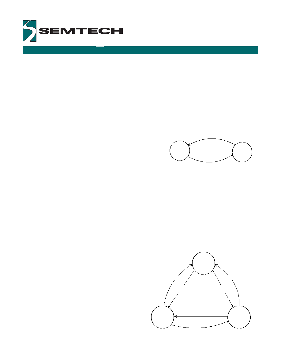
Self-Power ManagementTM
Self-Power ManagementTM of the UR7HCTS2 permits, independently of any system intervention, the lowest power
consumption possible within the present parameters and conditions of operation. Through Self-Power
ManagementTM, the UR7HCTS2 can operate on only 1 µA, most of the time, independently of the state of the
system.
The "Stop" mode is the lowest power consumption mode. In this mode, the oscillator is stopped and the
UR7HCTS2 consumes only leakage current. This is the default
mode, which the device enters when it is idle. An event or signal
condition wakes up the device. The UR7HCTS2 can still operate
most of the time at only 1 µA, even when the host is in the active
state, and with an active mouse attached to the UR7HCTS2's
external PS/2 port. If the external mouse sends a data packet, the
UR7HCTS2 enters "Run" mode for as long as it takes to process the
message and relay the information to the system. This operation is
done transparently to the host, without any data loss or any
response delay from the input device.
RUN
STOP
System Request To Send,
Mouse hot plug or Data Packet,
Touch Screen activity,
Button press
1s of inactivity
Figure 1:
Self-Power Management
TM
State
Host request
Screen activity
Button press
External PS/2 activity
System-coordinated Power Management
Note:
The UR7HCTS2 supports System-coordinated Power Management only in 4/8-wire sensor configurations.
Normal Operation State
In normal operation state, both the _PWR_DOWN and XPWRS pins are in high state. The UR7HCTS2 operations
are controlled by Self-Power ManagementTM.
Critical Suspend
At any time, the host may negate the _PWR_DOWN pin in order to force the device into a "critical suspend" mode.
This signal can be activated (driven low) due to specific conditions of the host's operations (for example, a
discharged battery), or due to actions of the operating
system or BIOS.
During the "critical suspend", the device shuts down all of
its pointing activities.
External PS/2 power down
The UR7HCTS2 monitors the state of the power supply rail
for the external PS/2 mouse through the XPWRS pin. If the
device senses that the external PS/2 mouse has been
powered-down by the host, it actively eliminates shot-
through current in the input buffers for the clock and data
lines by driving both low.
The UR7HCTS2 re-initializes the external PS/2 mouse
when power to the external PS/2 port is restored.
Critical Suspend
Ext Mouse
power down
Normal State
_PWR_DOWN=0
_PWR_DOWN=1
and XPWRS=1
_PWR_DOWN=0
_PWR_DOWN=1
and XPWRS=1
_PWR_DOWN=1
and XPWRS=0
_PWR_DOWN=1
and XPWRS=0
Figure 2:
System-coordinated Power Management

TOUCH SCREEN SENSOR INTERFACE
Copyright ©2000-2004 Semtech Corporation
UR7HCTS2 data sheet v1.14 (2004-10-28)
www.semtech.com
5
The UR7HCTS2 ScreenCoderÆ can acquire data from any 4-wire, 5-wire, or 8-wire resistive touch screen sensor.
Touch detection
If there is no touch, the IC does not perform measurements and does not send data to the system. When plate-to-
plate conductance is detected, the IC qualifies the touch based on the conductance detected. Semtech's proprietary
touch qualification algorithm works quickly (since data need not be collected over time for filtering), and
accommodates sensors with various plate-to-plate capacitances and impedances.
Touch Measurement (4/8-wire sensors)
Position information is collected only if the plate-to-plate conductance is sufficient for an accurate reading. To obtain
position information from the resistive touch screen sensor, the UR7HCTS2 uses four internal drivers (two pins for
each driver) and four sense lines. During sampling, the drivers of the X-axis are activated by setting one X-drive
high and the other X-drive low. The drivers for the Y-axis are set floating. This produces a voltage gradient across
the touch screen's surface in the X direction. The internal A/D measures both the voltage across the activated
X-plane and the voltage potential at the contact point. Next, the drivers for the Y-axis are activated while the drivers
for the X-axis are set floating. The internal A/D measures both voltage across the activated plane and potential at
the contact point. The X and Y absolute position is obtained from these four A/D measurements. The device keeps
monitoring the conductance even while the positioning data is being acquired. If insufficient conductance is
detected during sampling of the position, the current data set is rejected.
Touch Measurement (5-wire sensors)
Position information is collected only if the plate-to-plate conductance is sufficient for an accurate reading. The
5-wire touch screen has two layers. One is the resistive layer for supplying the voltage gradient. The other is the
conductive layer used to get the touch voltage. To obtain position information from the resistive touch screen
sensor, the UR7HCTS2 uses four internal drivers (two pins for each driver) and one sense line. During sampling,
the drivers for the top corners (northeast and northwest) are set high and the drivers for the bottom corners
(southeast and southwest) are set low. The sense plane is set floating. This produces a voltage gradient across the
touch screen's surface in the Y direction. The internal A/D measures both the voltage across the activated Y-plane
and the voltage potential at the contact point, determining the Y position. Next, the drivers for the left corners
(northwest and southwest) are set high and those for the right corners are set low. Again, the internal A/D measures
both voltage across the activated plane and potential at the contact point, determining the X position. The X and Y
absolute position is obtained from these A/D measurements.
Touch algorithm
Due to vibration and electrical noise, the raw data can not be used directly. Internal digital signal processing
delivers consistent position accuracy and quick touch response.
Resolution
The maximum touch screen resolution with the UR7HCTS2 is 1024 points per axis. Resolution varies somewhat for
different touch screen sensors, due to voltage droop on connecting wires from the parastic capacitance and
resistance of the sensor.
Speed
The UR7HCTS2 samples up to 100 points per second. Each point is one coordinate pair: an X value and a Y value.
Touch screens from different manufacturers
Operating parameters for touch screens from different manufacturers vary depending on the size of the sensor,
material it is made from, and mechanical construction. The UR7HCTS2 takes these properties into account, and
adjusts automatically for plate-to-plate capacitance, intrinsic plate resistances, etc.
Buttons
The UR7HCTS2 implements left and right buttons. The button information is combined with the external mouse's
button information when it is sent to the system.
Note:
Typically, the buttons are not used; they are implemented, and provided in the evaluation kit, as a
development aid.