Äîêóìåíòàöèÿ è îïèñàíèÿ www.docs.chipfind.ru
Juno
TM
04 UR8HC007-004
Zero-Power
TM
Input Device and
Power Management IC
Juno is a trademark of Semtech Corporation. All
other trademarks belong to their respective
companies.
Copyright @1998-2001 Semtech Corporation
DOC8-007-004-DS-103
www.semtech.com
1
HID & SYSTEM MANAGEMENT PRODUCTS, H/PC IC FAMILY
DESCRIPTION
FEATURES
RIGHT2/GIO66
RIGHT3/GIO67
C8
C9
C10
C11
GIO00/LED0
GIO01/LED1
GIO02/LED2
GIO03/LED3
VSS
OSCO
OSCI
C12
C13
RESET
VSS1
LID
PWROK
MOSI/RXD
1
80
61
20
21
40
41
60
GIO30/AD0
GIO43
GIO42/BLINKCANCEL
GIO41/SW1/±INT1
T
OUCHINT
HSUS
D
A1/PWM1/GIO51
D
A0/PWM0/GIO50
SS/R
TS
GIO11
GIO10
A
TN/CTS
SCLK/ISEL
MISO/TXD
R1
R0
BOT3/RIGHT
BOT2/LEFT
BOT1/BOT
BOT0/TOP
TOP3/RIGHTEN
TOP2/LEFTEN
TOP1/BOTEN
TOP0/TOPEN
VDD
AVREF
AVSS
TOPAD
BOTAD
LEFTAD
RIGHTAD
C15
C14
GIO31/AD1
R2
R3
R4
R5
R6
R7
C0
C1
C2
C3
C4
C5
C6
C7
LEFT0/GIO60
LEFT1/GIO61
LEFT2/GIO62
LEFT3/GIO63
RIGHT0/GIO64
RIGHT1/GIO65
UR8HC007-004-FQ
· Jupiter-class devices
· Professional H/PCs
· H/PCs
· Web Phones, G3 Terminals
The Juno
TM
04 is a member of a
series of input device and power
management companion ICs for
RISC-based portable systems. On
a single IC, the Juno
TM
04 integrates
control of any 4-wire or 8-wire
resistive touch screen, keyboard
scanning, unique power
management capabilities, and
plenty of General Purpose Input /
Output (GPIO).
The Juno
TM
04 provides continuous
operation between 3 and 5V and
scans a fully programmable 8 X 16
keyboard matrix.The Zero-Power
TM
Juno
TM
04 will power down even
between key presses. Typical
power consumption is less than 1
µA, a first for embedded ICs.
The Juno
TM
04 is equipped with
Semtech's proprietary protocol
developed specifically for RISC-
based handheld machines. It
interfaces the system via either
Asynchronous Serial (UART) or the
Serial Peripheral Interface (SPI).
The integration of features, many of
them programmable, on one IC
increases flexibility and reduces
component count and cost.
· Has additional GPIO available for
LEDs, switches, etc.
· Offers internal control of LCD
brightness/contrast, audio, etc. as
well as four 10-bit A/D channels
for power management monitoring
· Provides programmable features
that allow for maximum design
differentiation without
customization
· Cost-effective, reducing overall
system costs by integrating
features that would typically
require multiple components
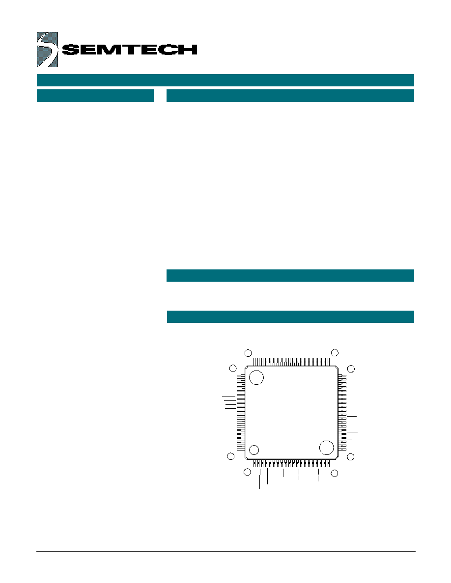
· Available in 80-pin 13 x 13 mm,
1.7mm high package to
accommodate slim designs
· Typically consumes less than 1µA
· Scans an 8 x 16 keyboard matrix
that supports Japanese, English
and European keyboards
· Interfaces any four- or eight-wire
resistive touch screen
· Operates continuously between 3
Volts and 5 Volts
· Offers unique power management
capabilities that work in harmony
with Windows® CE power modes
· Always runs in "Stop" mode without
data or event loss
· GPIO pins provide interrupt at both
falling and rising edge of signals,
ideal for lid functions, power, ring
indicators, docking signals, battery
measurement, etc.
APPLICATIONS
PIN ASSIGNMENTS
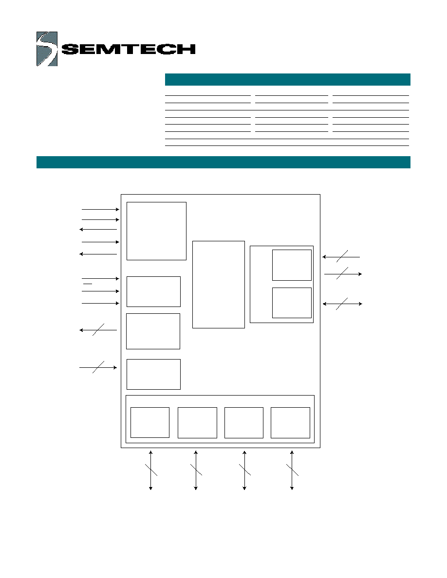
BLOCK DIAGRAM
ORDERING CODE
Copyright ©1998-2001 Semtech Corporation
DOC8-007-004-DS-103
www.semtech.com
2
GIO30-31 /
A/D0-1
Analog Outputs
PWM0-1
D/A0-1
GIO50-1
Power
Management
Unit
Configuration
Status and
Control
Registers
Dual Mode
Serial
Communications
Port
Analog Inputs
A/D0-1
(Shared with GIO3)
GIO00-03 /
LED0-3
GIO10-11
GIO41-43 /
SW / INT
Keyboard
Matrix
Scanner
SCLK / ISEL
MOSI/RxD
MISO/TxD
SS/RTS
ATN/CTS
PWROK
LID
HSUS
4
2
2
2
COL 0-15
ROW 0-7
2
3
TouchScreen
Port /
GIO60-7
21
HID Manager
G P I O
Package Options
Pitch in mm's
TA = 0° C to +75° C
80-pin, Plastic LQFP
0.5
UR8HC007-004-XX-FQ
Other Materials
Type
Order number
Technical Reference Manual
Document
DOC8-007-004-TR-XXX
Juno
TM
04 Eval. Kit
Evaluation Kit
EVK8-007-004-XXX
Note 1: XX= Optional for customization; XXX= Denotes revision number
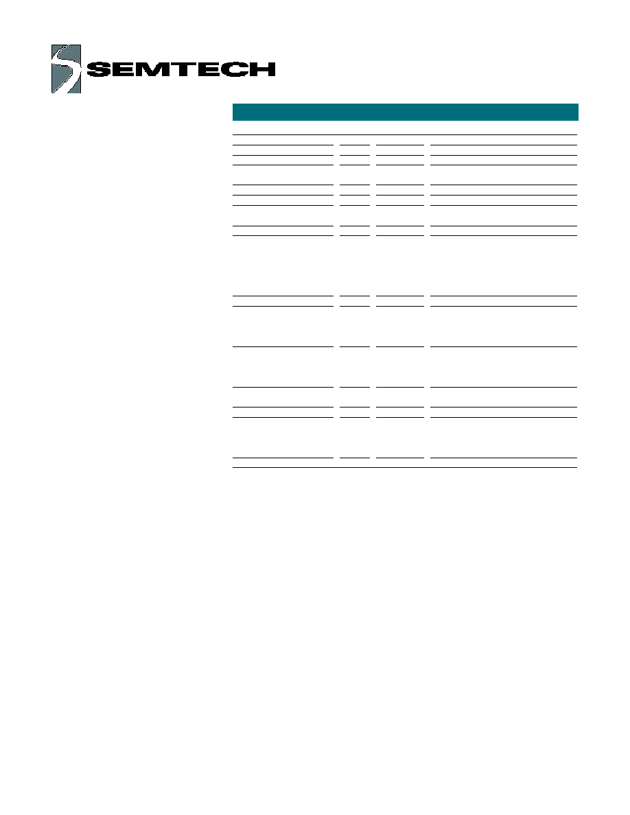
PIN DEFINITIONS
Copyright ©1998-2001 Semtech Corporation
DOC8-007-004-DS-103
www.semtech.com
3
Pin Numbers
Mnemonic
QFP
Type
Name and Function
Power Supply
VDD
71
PWR
Positive Supply Voltage
AVREF
72
AI
Positive analog reference
voltage
AVSS
73
PWR
Ground: analog signal
VSS
30
PWR
Ground: negative supply voltage
VSS1
24
PWR
Auxiliary Ground; must be tied to
pin 30
Reset
_RESET
25
I
Controller hardware reset pin:
when at Low-level, this pin holds the
UR8HC007in a reset state. This pin
must be held at a logic-low until Power
Supply voltage (VDD) reaches the
minimum operating level (2.7V).
Oscillator pins
OSCI
28
I
Oscillator input: connect ceramic
resonator with built-in load capacitors
or CMOS clock from external oscillator
4 MHz operating frequency
_OSCO
29
O
Oscillator Output: connect ceramic
resonator with built-in load capacitors
or keep open if external oscillator
is used
Scanned
matrix pins
ROW0-ROW7
62-55
I
Row matrix outputs
COL0-COL7
54-47
O
Column matrix outputs
COL8-COL11
38-35
COL12-COL13
27-26
COL14-COL15
79-78
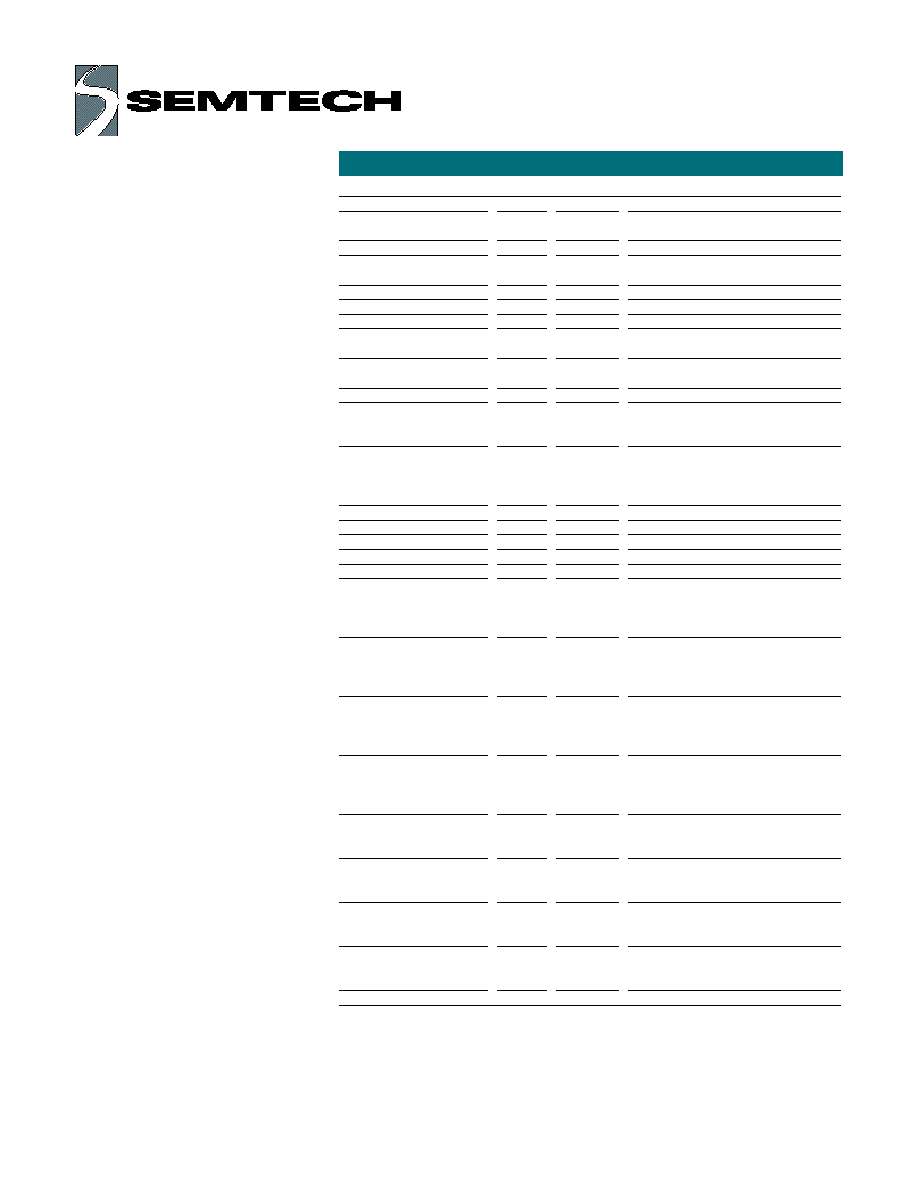
PIN DEFINITIONS, (CON'T)
Copyright ©1998-2001 Semtech Corporation
DOC8-007-004-DS-103
www.semtech.com
4
Pin Numbers
Mnemonic
QFP
Type
Name and Function
General Purpose
Input/Ouput
GIO0
GIO00/LED0-GIO3/LED3
34-31
I/O
General purpose input/output pin
LED driver
GIO1
GIO10-GIO11
17-16
I/O
General purpose input/output pin,
GIO3 - analog input
GIO30/AD0
1
I/O/Ai
General purpose input/output pin,
A/D input 0
GIO31/AD1
80
I/O/Ai
General purpose input/output pin,
A/D input 1
GIO4
GIO41/SW1/±INT1
4
I/O, I±Int
General purpose input/output pin,
switch Input. Capable of interrupt on
both positive and negative edges
GIO42/_BLINKCANCEL
3
I/O
General purpose input/output pin;
negative input cancels all LED
blinking, unless blink-cancel function
disabled in register
GIO43
2
I/O
General purpose input/output pin
GIO5 - analog output
DA0/PWM0/GIO50
11
Ao
D/A output (Range: AVSS to AVREF)
DA1/PWM1/GIO51
10
Ao
D/A output (Range: AVSS to AVREF)
Touch Screen interface
RIGHT3/GIO67
39
I/O
If no hardware touchscreen driver,
drive output to right side of
touchscreen; otherwise general
purpose I/O
RIGHT2/GIO66
40
I/O
If no hardware touchscreen driver,
drive output to right side of
touchscreen; otherwise general
purpose I/O
RIGHT1/GIO65
41
I/O
If no hardware touchscreen driver,
drive output to right side of
touchscreen; otherwise general
purpose I/O
RIGHT0/GIO64
42
I/O
If no hardware touchscreen driver,
drive output to right side of
touchscreen; otherwise general
purpose I/O
LEFT3/GIO63
43
I/O
If no hardware touchscreen driver,
drive output to left side of touchscreen;
otherwise general purpose I/O
LEFT2/GIO62
44
I/O
If no hardware touchscreen driver,
drive output to left side of touchscreen;
otherwise general purpose I/O
LEFT1/GIO61
45
I/O
If no hardware touchscreen driver,
drive output to left side of touchscreen;
otherwise general purpose I/O
LEFT0/GIO60
46
I/O
If no hardware touchscreen driver,
drive output to left side of touchscreen;
otherwise general purpose I/O
PIN DEFINITIONS, (CON'T)
Copyright ©1998-2001 Semtech Corporation
DOC8-007-004-DS-103
www.semtech.com
5
Pin Numbers
Mnemonic
QFP
Type
Name and Function
BOT3/RIGHT
63
O
If no hardware touchscreen driver,
drive output to bottom side of
touchscreen; otherwise output for right
side of touchscreen
BOT2/LEFT
64
O
If no hardware touchscreen driver,
drive output to bottom side of
touchscreen; otherwise output for left
side of touchscreen
BOT1/BOT
65
O
If no hardware touchscreen driver,
drive output to bottom side of
touchscreen; otherwise output for
bottom side of touchscreen
BOT0/TOP
66
O
If no hardware touchscreen driver,
drive output to bottom side of
touchscreen; otherwise output for top
side of touchscreen
TOP3/_RIGHTEN
67
O
If no hardware touchscreen driver,
drive output to top side of touchscreen;
otherwise enable output to right side of
touchscreen
TOP2/_LEFTEN
68
O
If no hardware touchscreen driver,
drive output to top side of touchscreen;
otherwise enable output to left side of
touchscreen
TOP1/_BOTEN
69
O
If no hardware touchscreen driver,
drive output to top side of touchscreen;
otherwise enable output to bottom side
of touchscreen
TOP0/_TOPEN
70
O
If no hardware touchscreen driver,
drive output to top side of touchscreen;
otherwise enable output to top side of
touchscreen
_TOUCHINT
5
I
Touchscreen interrupt input
RIGHTAD
77
Ai
A/D input from right side of
touchscreen
LEFTAD
76
Ai
A/D input from left side of touchscreen
BOTAD
75
Ai
A/D input from bottom side of
touchscreen
TOPAD
74
Ai
A/D input from top side of touchscreen
System and Power
Management
_LID
23
I±Int
Lid closed signal from the lid switch
(active-low). Capable of interrupt on
both positive and negative edges
PWROK
22
I±Int
Power OK signal. Capable of interrupt
on both positive and negative edges
_HSUS
9
I
Host Suspended signal (active-low).
When "Low," indicates that host
computer system is in power-reduced
or Stop mode.