
∑
221 WEST INDUSTRY COURT
∑
DEER PARK, NY 11729-4681
∑
PHONE (631) 586-7600
∑
FAX (631) 242-9798
∑
∑
World Wide Web - http://www.sensitron.com
∑
E-mail Address - sales@sensitron.com
∑
SENSITRON
SEMICONDUCTOR
Technical Data
Datasheet 4338, Rev A
HIGH VOLTAGE SILICON CARBIDE SINGLE PHASE FULL
WAVE BRIDGE
DESCRIPTION: 2500-VOLT, 5 AMP POWER SILICON CARBIDE SINGLE PHASE FULL WAVE BRIDGE
FEATURES:
∑
NO RECOVERY TIME OR REVERSE RECOVERY LOSSES
∑
NO TEMPERATURE INFLUENCE ON SWITCHING BEHAVIOR
∑
15000-VOLT HI-POT CAPABILITY
MAXIMUM RATINGS
ALL RATINGS ARE @ T
C
= 25
∞
C UNLESS OTHERWISE SPECIFIED.
RATING
SYMBOL
MAX.
UNITS
PEAK INVERSE VOLTAGE
PIV
2500
Volts
MAXIMUM DC OUTPUT CURRENT (With T
C
= 65
O
C) WHEN USED AS
A BRIDGE
I
O
5
Amps
MAXIMUM REPETITIVE FORWARD SURGE CURRENT
(t = 8.3ms, Sine) per leg, T
C
= 25
O
C
I
FRM
30
Amps
MAXIMUM NON-REPETITIVE FORWARD SURGE CURRENT
(t = 10
µ
s, pulse) per leg, T
C
= 25
O
C
I
FSM
100
Amps
MAXIMUM JUNCTION CAPACITANCE (V
r
=5V) per leg
C
T
240
pF
MAXIMUM POWER DISSIPATION, T
C
= 25
O
C P
d
100 W
MAXIMUM THERMAL RESISTANCE, Junction to Case
R
JC
0.5
∞
C/W
MAXIMUM OPERATING AND STORAGE TEMPERATURE RANGE
Top, Tstg
-55 to
+150
∞
C
ELECTRICAL CHARACTERISTICS
CHARACTERISTIC
TYP
MAX.
UNITS
MAXIMUM FORWARD VOLTAGE DROP (I
f
= 5 A PER LEG) V
f
T
J
=25
∞
C
T
J
=150
∞
C
5
7.5
5.50
9.00
Volts
MAXIMUM REVERSE CURRENT (2500V PIV PER LEG) I
r
T
J
= 25
∞
C
T
J
= 150
∞
C
0.05
0.10
0.40
2.00
mA
TOTAL CAPACITANCE CHARGE (V
R
=2500V, I
F
=5A, di/dt=500A/
µ
s and
T
J
=25
∞
C) Q
C
per leg
28 N/A
nC
SHB636053E
∑
221 WEST INDUSTRY COURT
∑
DEER PARK, NY 11729-4681
∑
PHONE (631) 586-7600
∑
FAX (631) 242-9798
∑
∑
World Wide Web - http://www.sensitron.com
∑
E-mail Address - sales@sensitron.com
∑
SENSITRON
Technical Data
Datasheet 4338, Rev A
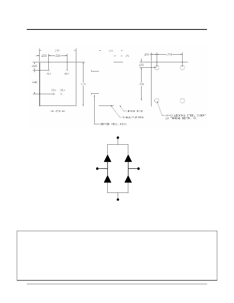
MECHANICAL DIMENSIONS (inches)
Application Note: Customers should be aware that at the current stage of technical development of SiC, the reverse avalanche
capabilities of the device are limited. Customer designs will need to accommodate these limitations and avoid exposure of the
device to this and other potentially damaging conditions in their applications.
SHB636053E
DISCLAIMER:
1- The information given herein, including the specifications and dimensions, is subject to change without prior notice to improve product characteristics. Before
ordering, purchasers are advised to contact the Sensitron Semiconductor sales department for the latest version of the datasheet(s).
2- In cases where extremely high reliability is required (such as use in nuclear power control, aerospace and aviation, traffic equipment, medical equipment , and
safety equipment) , safety should be ensured by using semiconductor devices that feature assured safety or by means of users' fail-safe precautions or other
arrangement .
3- In no event shall Sensitron Semiconductor be liable for any damages that may result from an accident or any other cause during operation of the user's units
according to the datasheet(s). Sensitron Semiconductor assumes no responsibility for any intellectual property claims or any other problems that may result from
applications of information, products or circuits described in the datasheets.
4- In no event shall Sensitron Semiconductor be liable for any failure in a semiconductor device or any secondary damage resulting from use at a value exceeding
the absolute maximum rating.
5- No license is granted by the datasheet(s) under any patents or other rights of any third party or Sensitron Semiconductor.
6- The datasheet(s) may not be reproduced or duplicated, in any form, in whole or part, without the expressed written permission of Sensitron Semiconductor.
7- The products (technologies) described in the datasheet(s) are not to be provided to any party whose purpose in their application will hinder maintenance of
international peace and safety nor are they to be applied to that purpose by their direct purchasers or any third party. When exporting these products (technologies),
the necessary procedures are to be taken in accordance with related laws and regulations.
DC+
DC-
AC1
AC2